
2 layers33.7 × 97.8 mm
HAN ESP TSS721
UtilitechAS/amsreader-firmware
ESP8266 and ESP32 compatible firmware to read, interpret and publish data to MQTT from smart electrical meters, both DLMS and DSMR is supported
29 parts470

 tlouden/uplift-iot5
Uplift is an open-source printed circuit board by tlouden, from the tlouden/uplift-iot repository on GitHub, published under the MIT licence. It is a 2-layer board of 52.1 × 58.4 mm with 11 parts on 36 nets, routed with 82 tracks and 4 vias.
It is built around the RJ45. Its parts include 3 resistors, 2 connectors and 1 IC. It belongs with the ESP32 boards of this library.
Connecting an UPLIFT desk to Home Assistant using an ESP32 with ESP Home for Home Assistant.
This is an adversarial interop against a hardware interface. Any changes from the manufacturer could invalidate or even make this dangerous. Validate assumptions on your own system and proceed with caution.
The UART driver for ESP Home should work without modification. Everything else will need to be customized to your setup using the provided examples.
An ESP32 is used with ESP Home. The specific board is a esp32doit-devkit-v1.
Custom UART driver that interprets the data from the UPLift desk unit.
An example definition for the device in ESPHome. Will need to be customized to be used.
Data is consumed by Home Assistant.
An example automation which will need to be cusomized to be used.
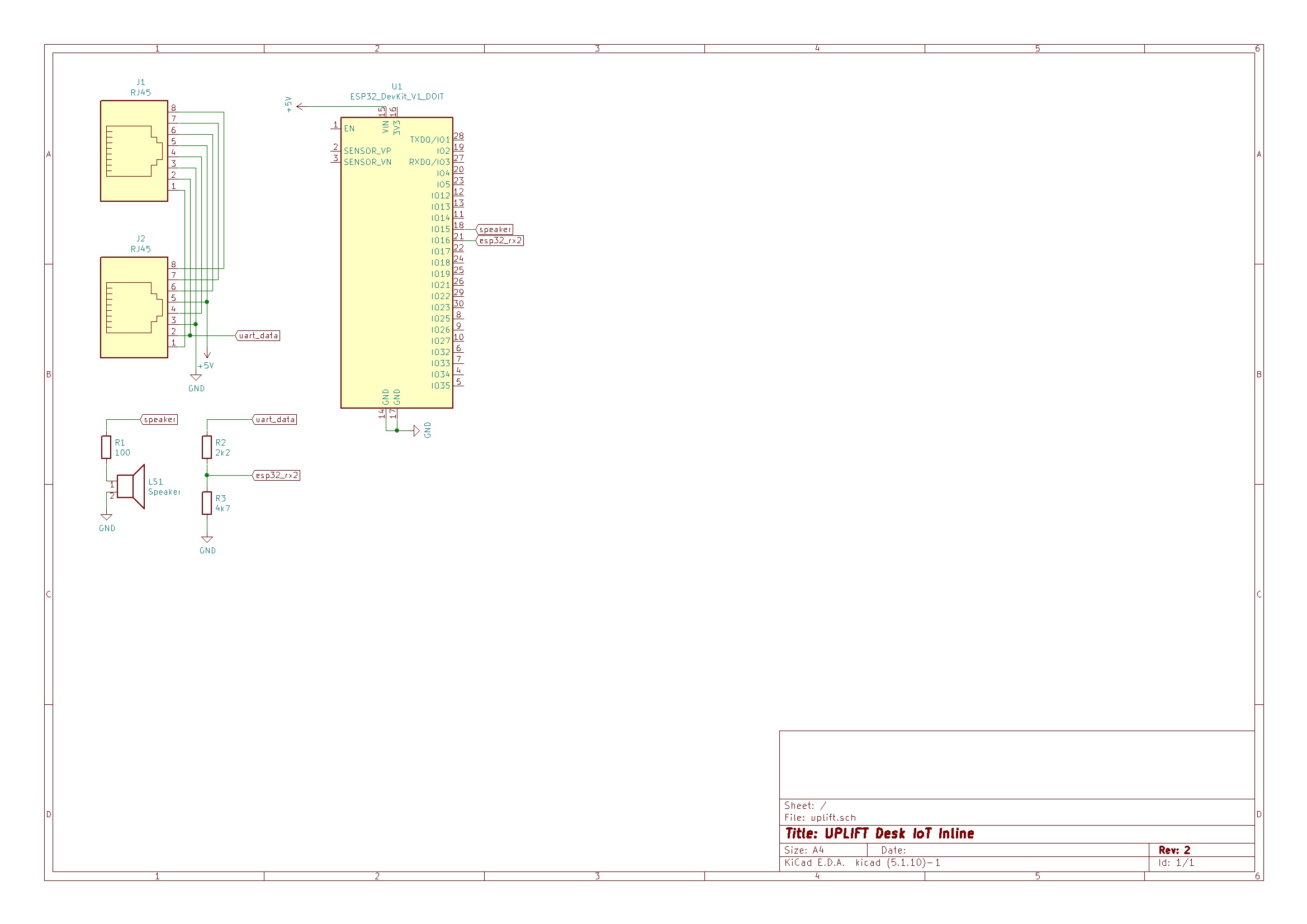
KiCAD files for a PCB are included for anyone that would like to produce their own. Here is the schematic if you'd like to breadboard it.
OpenSCAD files for an enclosure are included for 3D printing. The default values are good even if you use a header to connect the ESP to the board. Use M3x4mm screws to attach the PCB. The lid will snap fit. The BOSL2 library is used and included along with it's license file.
On My UPLIFT Desk, the keypad communicates with the motor box via an ethernet cable. A logic analyser shows that the second wire has a digital signal at 9600 baud. The third wire is ground, and the fifth is a 5v supply. All the others get pulled low by the keypad when buttons are pressed.
I don't want remote control of the motors, so my analysis is focused exlusively on the serial data on line 2. The data only sends few a short period after the desk height changes, then goes dead. This isn't a problem, but is good to know when doing analysis. Starting with defaults for parity, stop bits, and data length produced the data sequence 1, 1, [0,1], [0-255] repeating. The format is big endian, so the first integer is always 257 and the second is the real data. It is sending the height in tenths of an inch, so 296 is 29.6".
A simple approach is used for such a simple use case. We look for the expected 1,1 data sequence and then process the next two bytes. It is possible to get out of sequence when the desk is higher than 25.5" so if the first byte is not a 0 or 1, the logic resets to avoid non-sensical readings like 1000". This allows up to 51.1" to be expressed, and my desk only goes up to 50.8".
| Qty | Value | Footprint | References |
|---|---|---|---|
| 1 | 100 | Resistor_THT:R_Axial_DIN0207_L6.3mm_D2.5mm_P10.16mm_Horizontal | R1 |
| 1 | 2k2 | Resistor_THT:R_Axial_DIN0207_L6.3mm_D2.5mm_P10.16mm_Horizontal | R2 |
| 1 | 4k7 | Resistor_THT:R_Axial_DIN0207_L6.3mm_D2.5mm_P10.16mm_Horizontal | R3 |
| 1 | ESP32_DevKit_V1_DOIT | ESP32_DevKit_V1_DOIT:esp32_devkit_v1_doit | U1 |
| 1 | RJ45 | Connector_RJ:RJ45_Amphenol_54602-x08_Horizontal | J2 |
| 1 | RJ45 | Connector_RJ:RJ45_Amphenol_54602-x08_Horizontal-ALT-Silk | J1 |
| 1 | Speaker | Buzzer_Beeper:MagneticBuzzer_ProSignal_ABT-410-RC | LS1 |
The 7 most common of 11 parts.
It measures 52.1 × 58.4 mm and has 2 copper layers, 1.6 mm thick.
11 parts, built around the RJ45. The full list of its parts is on this page, with links to each part's symbol and footprint where PCBKit's library has them.
From the tlouden/uplift-iot repository on GitHub, at the commit this page was made from: the board is board/uplift.kicad_pcb. PCBKit opens the board in the browser, with nothing to install.
Its repository publishes it under the MIT licence: you may reuse it on that licence's terms (keep the author's notice, and for a copyleft licence share your changes alike).
UtilitechAS/amsreader-firmware
ESP8266 and ESP32 compatible firmware to read, interpret and publish data to MQTT from smart electrical meters, both DLMS and DSMR is supported

travisgoodspeed/goodfet
An embedded bus adapter for various microcontrollers and radios.


nv1t/standing-desk-interceptor
I wanted to intercept the communication between my Flexispot standing desk buttons. This is the progress on the project


Severson-Group/AMDC-Hardware
Circuit board designs for controlling advanced motor systems

mfkiwl/KiwiSDR_PCB
KiCAD PCB files for KiwiSDR project including active antenna and bias tee