2 layers30 × 61.6 mm
Sniffer
OpenRemise/Sniffer
The Sniffer is a small add-on board that turns a Raspberry Pi Pico into a DCC (and BiDi) logic analyzer.
45 partsCERN-OHL-W-2.0

 tjko/fan-test-adapter5
Adapter PCB board for easily testing PC (PWM) fans.
Fan test adapter is an open-source printed circuit board by tjko, from the tjko/fan-test-adapter repository on GitHub, published under the GPL-3.0 licence. It is a 2-layer board of 145 × 65 mm with 75 parts on 27 nets, routed with 373 tracks and 10 vias.
It is built around the FM4007-W-TMS, SBRT5A50SA and SM5819PL-TP, with the 2N7002K among its other parts. Its parts include 16 connectors, 15 resistors, 12 diodes, 11 capacitors and 2 transistors. It belongs with the interfaces and adapters boards of this library.


Adapter PCB board for easily testing PC (PWM) fans.
Adapter was created to simplify characterising PC fans. It's mainly meant for PWM fans, but can also be useful for 3-pin PC fans. Adapter also has common JST connectors for common 2-pin fans. This adapter was used in development and testing of Fanpico (Fanpico is a smart PWM fan controller) to "emulate" motherboard FAN outputs.
Adapter is meant to be used with
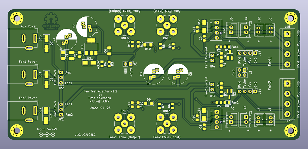
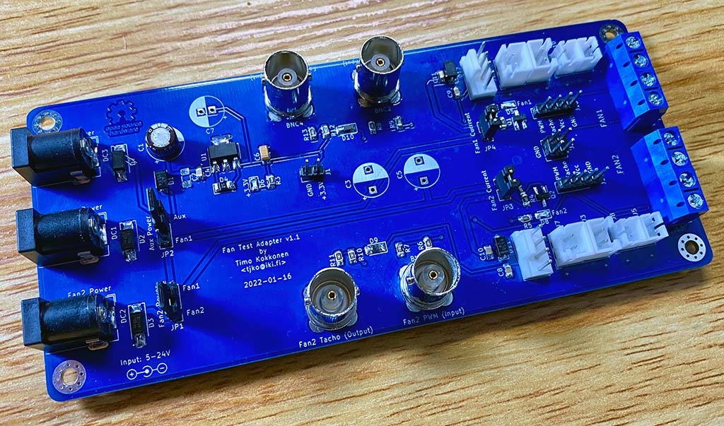
Assembled fan test adapter:
Fan test adapter in use:
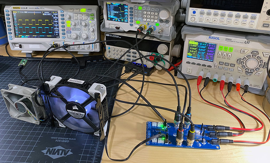
This is only adapter for easily testing/controlling PWM fans. If used incorrectly it could easily damage your fans, etc...
Fan Test Adapter has three DC power jacks. It can be used only with power supplied to "Fan1 Power" jack, but it may be desirable to use all three, depending on how adapter is being used.
This is can be used to power the board itself (3.3V power rail, LEDs, etc). This can be useful if doing fan power consumption measurements via measuring supplied power to Fan1/Fan2 connectors. When using this connector make sure jumper Aux Power is set to Aux position (and Fan2 Power jumper is set to Fan2 position).
Recommended supply voltage is 5V (however up to 24V can be used if needed).
This is used to provide power to Fan1. Additionally Aux Power jumper can be set to Fan1 position if AUX Power is not used.
Recommended supply voltage is the nominal voltage of the fan being tested (Voltage should be in range from 5V to 24V max).
This is used to proive power fo Fan1. If this connector is used remember to set Fan2 Power jumper to Fan2 position.
Recommended supply voltage is the nominal voltage of the fan being tested (Voltage should be in range from 5V to 24V max).
Normally closed. Can be used for precise current measurement of Fan1 power consumption, by removing the jumper and connecting current meter in the pins.
Normally closed. Can be used for precise current measurement of Fan2 power consumption, by removing the jumper and connecting current meter in the pins.
Jumper to select whether board itself (3.3V power rail) is powered from Fan1 Power or Aux Power power connector.
Jumper to select whether Fan2 is powered from Fan1 Power or Fan2 Power power connector.
Input for PWM signal to control fan speed. Typically (with PC fans) this is 25kHz PWM signal (0-5V).
Adapter generates 3.3V TTL signal from the open collector tachometer output of the fan. So this is generally safe to be read direcly with a 3.3V (or 5V) MCU.
Kerber files ready to be sent to a PCB maker (like JLCPCB, etc):
Currently this is only a DIY project. However PCBs are occasionally available (in limited quantities) at: eBay
| Qty | Value | Footprint | References |
|---|---|---|---|
| 4 | 10k | Resistor_SMD:R_0805_2012Metric_Pad1.15x1.40mm_HandSolder | R1, R4, R10, R12 |
| 4 | 1k | Resistor_SMD:R_0805_2012Metric_Pad1.15x1.40mm_HandSolder | R6, R8, R11, R13 |
| 4 | MountingHole_Pad | MountingHole:MountingHole_3.2mm_M3_Pad_Via | H1, H2, H3, H4 |
| 3 | 5k | Resistor_SMD:R_0805_2012Metric_Pad1.15x1.40mm_HandSolder | R2, R3, R5 |
| 3 | FM4007W | Diode_SMD:D_SMA | D4, D11, D12 |
| 3 | LED | LED_SMD:LED_0805_2012Metric_Pad1.15x1.40mm_HandSolder | D5, D6, D8 |
| 3 | SBRT5A50SA | Diode_SMD:D_SMA_Handsoldering | D2, D3, D7 |
| 3 | SM5819PL-TP | Diode_SMD:D_1206_3216Metric_Pad1.42x1.75mm_HandSolder | D1, D9, D10 |
| 2 | 0.1uF | Capacitor_SMD:C_0805_2012Metric_Pad1.15x1.40mm_HandSolder | C10, C11 |
| 2 | 1M | Resistor_SMD:R_0805_2012Metric_Pad1.15x1.40mm_HandSolder | R14, R15 |
| 2 | 1nF | Capacitor_SMD:C_0805_2012Metric_Pad1.15x1.40mm_HandSolder | C8, C9 |
| 2 | 2N7002K | Package_TO_SOT_SMD:SOT-23_Handsoldering | Q1, Q2 |
| 2 | 33k | Resistor_SMD:R_0805_2012Metric_Pad1.15x1.40mm_HandSolder | R7, R9 |
| 2 | DNF | Capacitor_THT:CP_Radial_D10.0mm_P2.50mm_P5.00mm | C3, C5 |
| 1 | 0.1uF 35V | Capacitor_SMD:C_0805_2012Metric_Pad1.15x1.40mm_HandSolder | C4 |
| 1 | 10uF | Capacitor_SMD:C_1206_3216Metric_Pad1.42x1.75mm_HandSolder | C6 |
| 1 | 10uF | Capacitor_THT:CP_Radial_D10.0mm_P2.50mm_P5.00mm | C7 |
| 1 | 10uF 35V | Capacitor_THT:CP_Radial_D10.0mm_P2.50mm_P5.00mm | C1 |
| 1 | 3.3V Output | Connector_PinHeader_2.54mm:PinHeader_1x02_P2.54mm_Vertical | J1 |
| 1 | 4.7uF 35V | Capacitor_SMD:C_1210_3225Metric_Pad1.42x2.65mm_HandSolder | C2 |
| 1 | Aux Power | Connector_BarrelJack:BarrelJack_Wuerth_6941xx301002 | DC3 |
| 1 | Aux Power | Connector_PinHeader_2.54mm:PinHeader_1x03_P2.54mm_Vertical | JP2 |
| 1 | Extra GND Pins | Connector_PinHeader_2.54mm:PinHeader_2x02_P2.54mm_Vertical | J2 |
| 1 | Fan1 | Connector:FanPinHeader_1x04_P2.54mm_Vertical | J12 |
| 1 | Fan1 Currrent | Connector_PinHeader_2.54mm:PinHeader_1x02_P2.54mm_Vertical | JP4 |
| 1 | Fan1 PWM (Input) | Connector_Coaxial:BNC_TEConnectivity_1478204_Vertical | BNC2 |
| 1 | Fan1 Power | Connector_BarrelJack:BarrelJack_Wuerth_6941xx301002 | DC1 |
| 1 | Fan1 Tacho (Output) | Connector_Coaxial:BNC_TEConnectivity_1478204_Vertical | BNC4 |
| 1 | Fan1_Header | Connector_PinHeader_2.54mm:PinHeader_1x04_P2.54mm_Vertical | J16 |
| 1 | Fan1_JST1 | Connector_JST:JST_XH_B2B-XH-A_1x02_P2.50mm_Vertical | J9 |
| 1 | Fan1_JST2 | Connector_JST:JST_XH_B2B-XH-A_1x02_P2.50mm_Vertical | J4 |
| 1 | Fan1_JST3 | Connector_JST:JST_PH_B2B-PH-K_1x02_P2.00mm_Vertical | J10 |
| 1 | Fan1_JST4 | Connector_JST:JST_PH_B2B-PH-K_1x02_P2.00mm_Vertical | J6 |
| 1 | Fan1_Terminal | TerminalBlock:TerminalBlock_bornier-4_P5.08mm | J15 |
| 1 | Fan2 | Connector:FanPinHeader_1x04_P2.54mm_Vertical | J11 |
| 1 | Fan2 Current | Connector_PinHeader_2.54mm:PinHeader_1x02_P2.54mm_Vertical | JP3 |
| 1 | Fan2 PWM (Input) | Connector_Coaxial:BNC_TEConnectivity_1478204_Vertical | BNC1 |
| 1 | Fan2 Power | Connector_PinHeader_2.54mm:PinHeader_1x03_P2.54mm_Vertical | JP1 |
| 1 | Fan2 Power | Connector_BarrelJack:BarrelJack_Wuerth_6941xx301002 | DC2 |
| 1 | Fan2 Tacho (Output) | Connector_Coaxial:BNC_TEConnectivity_1478204_Vertical | BNC3 |
| 1 | Fan2_Header | Connector_PinHeader_2.54mm:PinHeader_1x04_P2.54mm_Vertical | J14 |
| 1 | Fan2_JST1 | Connector_JST:JST_XH_B2B-XH-A_1x02_P2.50mm_Vertical | J7 |
| 1 | Fan2_JST2 | Connector_JST:JST_XH_B2B-XH-A_1x02_P2.50mm_Vertical | J3 |
| 1 | Fan2_JST3 | Connector_JST:JST_PH_B2B-PH-K_1x02_P2.00mm_Vertical | J8 |
| 1 | Fan2_JST4 | Connector_JST:JST_PH_B2B-PH-K_1x02_P2.00mm_Vertical | J5 |
| 1 | Fan2_Terminal | TerminalBlock:TerminalBlock_bornier-4_P5.08mm | J13 |
| 1 | SPX2954-3.3 | Package_TO_SOT_SMD:SOT-223-3_TabPin2 | U1 |
The 72 most common of 75 parts.
OpenRemise/Sniffer
The Sniffer is a small add-on board that turns a Raspberry Pi Pico into a DCC (and BiDi) logic analyzer.

SunDevilRocketry/Flight-Computer
General purpose flight computer for high powered rocketry projects.

gasiepgodoy/Open-Source-PLC
Open Source Programmable Logic Controller (Hardware and Software). Based on the Master of Science in Electrical Engineering of João Vitor Rocha Santana

cacost12/SDR-Flight-Computer-Lite-PCB
Current PCB Revision: 1.0 PCB Part Number: A0007

SunDevilRocketry/Liquid-Engine-Controller
Main microcontroller board for embedded control of SDR's liquid bipropellant engine.

SunDevilRocketry/Wheatstone-Bridge
Pressure transducer signal emulation board to facilitate electronics testing

rimio/cat-a-hack
Prototyping board for PC/μC to transceiver isolation.

It measures 145 × 65 mm and has 2 copper layers, 1.6 mm thick.
75 parts, built around the FM4007-W-TMS, SBRT5A50SA, SM5819PL-TP and 2N7002K. The full list of its parts is on this page, with links to each part's symbol and footprint where PCBKit's library has them.
From the tjko/fan-test-adapter repository on GitHub, at the commit this page was made from: the board is fan-test-adapter.kicad_pcb. PCBKit opens the board in the browser, with nothing to install.
Its repository publishes it under the GPL-3.0 licence: you may reuse it on that licence's terms (keep the author's notice, and for a copyleft licence share your changes alike).