4 layers337.6 × 105.7 mm
ISA CGA
hkzlab/CGA_Redux
The Color Graphics Adapter Redux board is a more or less faithful clone of the original IBM CGA, based on the original schematics
170 parts56
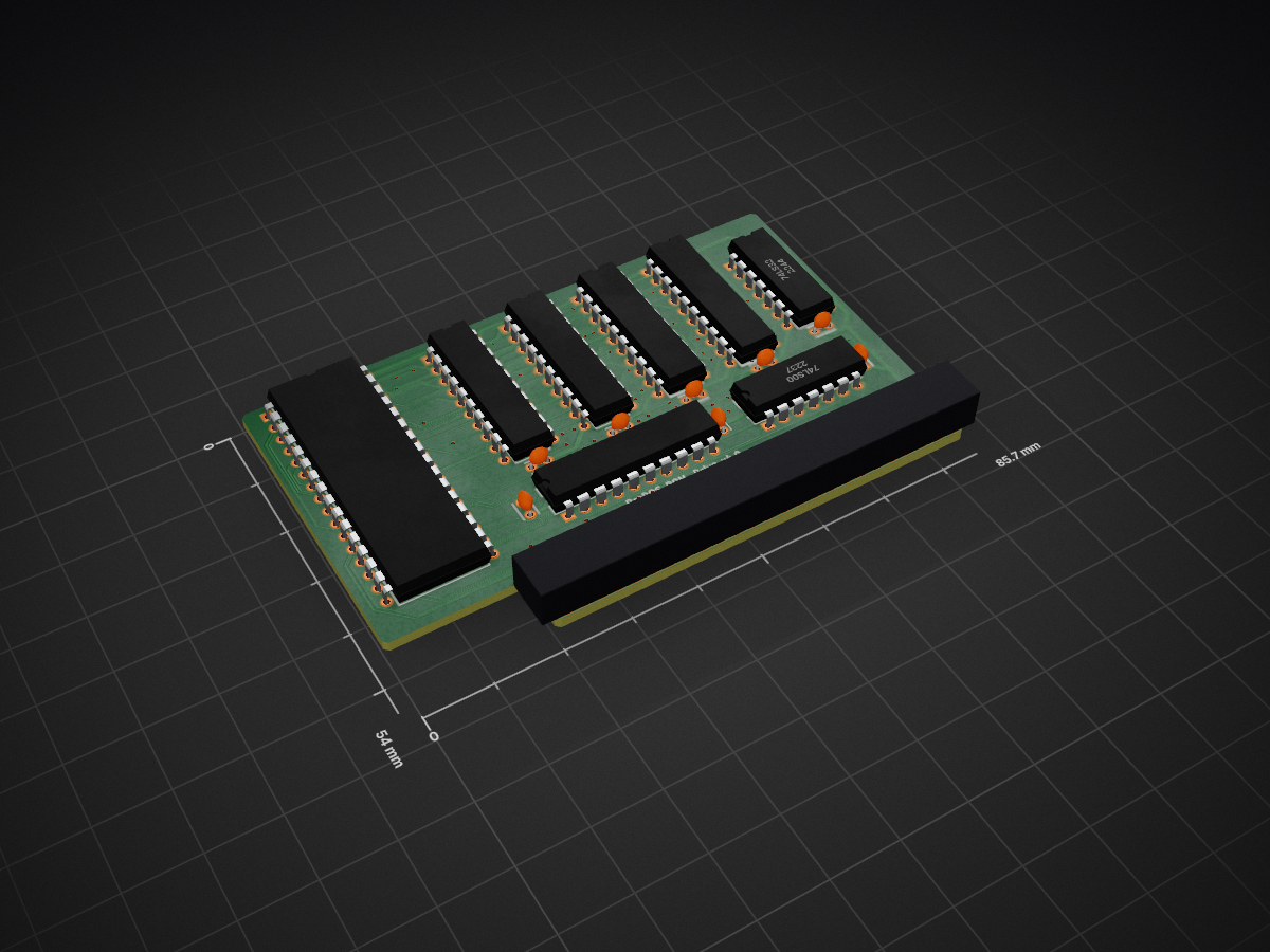
 tjboldt/ProDOS-ROM-Drive77
A bootable 1 MB solid state disk for Apple ][ computers
ProDOS ROM Drive is an open-source printed circuit board by tjboldt, from the tjboldt/ProDOS-ROM-Drive repository on GitHub, published under the MIT licence. It is a 2-layer board of 85.7 × 54 mm with 17 parts on 80 nets, routed with 1,176 tracks and 101 vias.
It is built around the 74LS245SC, 74LS00SC and 74LS32SC, with the 74LS374PC among its other parts. Its parts include 8 capacitors, 2 ICs and 1 connector.


This is a new revision of the hardware, incompatible with previous firmware and drive image before v3. If you have a v2.5 board, see the v2.5 tag here. Note that all of v2.1, v2.5 and v3.0 have a small design mistake that didn't properly buffer the data bus the way it was intended in the original v1.0 version. This has been fixed for v4.0.
This is a peripheral card for the Apple ][ series computers that acts as a read-only solid state disk drive (SSD) all in EPROM. Although it won't run DOS, it is fully ProDOS compatible and will appear as a read-only hard drive even when booting from another drive. It holds 1024 KB of disk data with the 256 byte firmware stored in block 0001 where the SOS boot loader normally resides. The drive boots ProDOS and into BASIC in under 1.5 seconds.
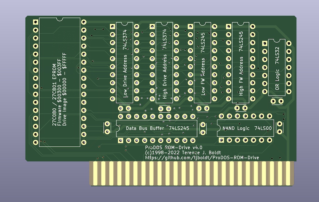
You can order blank circuit boards from PCBWay or upload the provided gerber and drill files to any PCB manufacturer.
My first Apple computer was an Apple //e that my brother bought in early 1984. Countless hours were spent playing games which developed my interest in building games. This also led to the creation of various utilities to help organize disks or just to see what could be done while programming.
As time passed, I obtained other machines far more powerful and eventually my once loved Apple IIe got used less and less. I did still pull it out of storage every few months to play some classic games or see what I could accomplish with greater programming skills. The problem was connecting up disk drives, looking for disks and hoping that the disks still worked. To make life simpler, I decided I needed to come up with some way to permanently store the files inside the computer without needing to plug in anything but the power and video connectors. This is where the idea for a solid-state drive began.
In the summer of 1998 I did some research in my own Apple II library for information on building peripheral cards. I drew up some designs in September 1998 and started building a prototype on a solderless breadboard with the wires jumpered over from a dead parallel card which I had cut the traces on. The rough idea at the time was to have two EPROMs. One would hold the 256 bytes of code in the $Cs00 - $CsFF space (where s is the slot number) and the second EPROM would get accessed through the 16 byte port space for the slot. To access more than 16 bytes, I would have a couple latch chips where you could program in the address of the disk EPROM and then read it one byte at a time through the ports. Originally I was going to make my own modified version of DOS 3.3 but before I got too far, David Wilson from Australia convinced me that it was much easier to build it for ProDOS since it supported many types of drives natively.
By November 1998 I had a prototype on the solderless breadboard that could read data from the EPROM but it had no driver code, didn't boot and was very unreliable. In December I managed to have the two EPROM based system running but it would fail to boot about 80% of the time with various read errors. Shortening the length of wires, cleaning up the layout and a new design helped but it was still unreliable. I finally gave up on the second design but as it turns out, it could have been fixed quite easily.
By mid-May of 1999 I finally got around to building a third design. This time I reduced the chip count and made the firmware for the drive reside in the top two blocks of the virtual disk EPROM. It still was somewhat unreliable in slot one but it was progressively worse as it was placed into higher slot numbers. By slot seven the card was completely unuseable. I then discovered that adding a 104 ceramic capacitor to each chip made the problem disappear. It was suddenly fully reliable.
To build actual circuit boards, I tried making some by hand with marker, etching solution and copper on fibreglass boards but this proved to be far too difficult. I then learned the wonders of gerber files which can be created with a variety of PCB layout software. The files were emailed to a company in Alberta, Canada and three days later in July of 1999 I received a batch of 10 blank boards. These boards did not have the familiar green board look to them, nor were they pre-cut. I had to cut and file them to fit an Apple II slot by hand. Back then it was prohitively expensive for a young hobbiest to make less than 20 or 30 boards with the full solder-masking process due to the set-up fees.
In 2019, I decided to revisit the original design as I was disappointed that the original didn't have a solder mask and was rather large for what it was. I got the board much smaller but in the process of translating my two decade old hand written notes, I made a mistake on one control line. To actually call this project finished, I had to make another revision. I also noticed the revised board was slightly larger than a credit card so I worked for a couple weeks to optimize the lines and squeeze the two-layer board down to 3.375" x 2.125". (Note that references above to first, second and third design are all the solderless breadboard prototypes leading up to the 1.0 circuit board printed in 1999, 2.0 was never made, 2.1 is the board with the error patched with a jumper wire and 2.2 through 2.4 were never made).
In 2021, the first ever issue was opened on the project requesting that the firmware be relocatable. I let that issue sit for a few months and then Ralle Palaveev supplied some relocatable firmware as a patch. I quickly realized that this could be placed into the second block on the drive normally reserved for SOS bootloader for the Apple ///, essentially allowing the full EPROM to be used for the drive. I disassembed Ralle's patch, merged it into the existing source code and made a few updates to save a few bytes and add clarity. This change required some differences in wiring for the firmware addressing on the card. The final revision 4.0 was made in 2022 to fix the data buffer wiring but was otherwise the same as 3.0.
I used to use Ciderpress to copy files onto the drive image but now use my own cross-platform command line tool ProDOS-Utilities and sometimes make modifications to the image live via an Apple II emulator. I then burn the file to a 27C801 EPROM with a GQ-4x4 USB Programmer. Do NOT overwrite block 0001 in the image as it contains the firmware for the card.
If you're planning on designing you own card, I highly recommend reading "Interfacing & Digital Experiments with your Apple" by Charles J. Engelisher and Apple's "Apple II Reference Manual" as well as "ProDOS Technical Reference Manual" if you want to build a drive. You also need an EPROM programmer, some chips and a prototyping board. My designs used simple logic gates to decode addresses but if you want to reduce chip count, you'll also need a PAL/GAL logic programmer (which some EPROM programmers can do).
Official website is apple2.ca.
I generally no longer sell these cards but you can buy them online from Laser and other retailers.
| Qty | Value | Footprint | References |
|---|---|---|---|
| 8 | 0.1µF | Capacitor_THT:C_Disc_D3.0mm_W2.0mm_P2.50mm | C1, C2, C3, C4, C5, C6, C7, C8 |
| 3 | 74LS245 | Package_DIP:DIP-20_W7.62mm | DataBuffer1, HiAddrBuffer1, LowAddrBuffer1 |
| 2 | 74LS374 | Package_DIP:DIP-20_W7.62mm | HiAddrLatch1, LowAddrLatch1 |
| 1 | 27C080 | Package_DIP:DIP-32_W15.24mm | EPROM1 |
| 1 | 74LS00 | Package_DIP:DIP-14_W7.62mm | U1 |
| 1 | 74LS32 | Package_DIP:DIP-14_W7.62mm | U2 |
| 1 | Apple II Expansion Slot | Connector:Apple II Expansion Edge Connector | J1 |
hkzlab/CGA_Redux
The Color Graphics Adapter Redux board is a more or less faithful clone of the original IBM CGA, based on the original schematics


fortinsylvain/MyCpu
Home brew CPU Hardware with 1-bit ALU implementation using 74LSxx, a micro-code and assembler coded in C#.


RetroStack/Sorcerer_DreamDisk
Exidy Sorcerer/MicroBee DreamDisk Disk Controller


It measures 85.7 × 54 mm and has 2 copper layers, 1.6 mm thick.
17 parts, built around the 74LS245SC, 74LS00SC, 74LS32SC and 74LS374PC. The full list of its parts is on this page, with links to each part's symbol and footprint where PCBKit's library has them.
From the tjboldt/ProDOS-ROM-Drive repository on GitHub, at the commit this page was made from: the board is Hardware/ProDOS ROM-Drive.kicad_pcb and its schematic Hardware/ProDOS ROM-Drive.kicad_sch. PCBKit opens the board in the browser, with nothing to install.
Its repository publishes it under the MIT licence: you may reuse it on that licence's terms (keep the author's notice, and for a copyleft licence share your changes alike).