8 layers42.2 × 67.2 mm
OBC PCB
timohueser/OpenBikeComputer
Open source Bikecomputer with a focus on exploration and adventure.
186 parts11GPL-3.0
 timohueser/OpenBikeComputer11
Open source Bikecomputer with a focus on exploration and adventure.
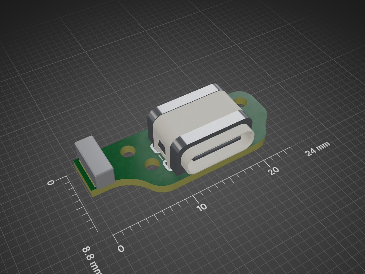
USB Baseboard is an open-source printed circuit board by timohueser, from the timohueser/OpenBikeComputer repository on GitHub, published under the GPL-3.0 licence. It is a 2-layer board of 24 × 8.7 mm with 5 parts on 12 nets.
It is built around the TPD4E05U06DQAR, TPD1E05U06DYAR and USB4730-GF-A. Its parts include 2 connectors, 1 capacitor, 1 IC and 1 diode. It belongs with the computers and single-board computers boards of this library.


Open OBC_PCB.kicad_pro in KiCad 10. Keep the project library tables with the files.
Run electrical checks from this directory:
kicad-cli sch erc --format json -o /tmp/obc-erc.json OBC_PCB.kicad_sch
kicad-cli pcb drc --schematic-parity --format json -o /tmp/obc-drc.json OBC_PCB.kicad_pcbThis table describes the main PCB. The firmware README
describes the development kit. Port the firmware pin assignments before running it on this board.
LCD_*_MCU is the net between U6 and its source resistor; LCD_* continues to J1.
| Device | Pad | GPIO | Signal | Connection |
|---|---|---|---|---|
| U6 | 1 | P2.01 | SD_CLK | R9, 33 Ω at U6; fixed SD pin |
| U6 | 2 | P2.02 | SD_D0 | Fixed SD pin |
| U6 | 3 | P2.03 | SD_D2 | Fixed SD pin |
| U6 | 4 | P2.04 | SD_D1 | Fixed SD pin |
| U6 | 5 | P2.05 | SD_CMD | Fixed SD pin |
| U6 | 7 | P1.29 | COM_SOURCE | |
| U6 | 8 | P1.30 | LCD_R0 | R69, 100 Ω at U6 |
| U6 | 9 | P1.31 | LCD_R1 | R70, 100 Ω at U6 |
| U6 | 10 | P1.00 | BUZZER_PWM | |
| U6 | 11 | P1.01 | LCD_GSP | R77, 220 Ω at U6 |
| U6 | 12 | P1.02 | LCD_GEN | R78, 220 Ω at U6 |
| U6 | 13 | P1.03 | LCD_BSP | R80, 220 Ω at U6 |
| U6 | 14 | P1.04 | LCD_GCK | R76, 220 Ω at U6 |
| U6 | 15 | P1.05 | LCD_BCK | R75, 100 Ω at U6 |
| U6 | 16 | P1.06 | LCD_G0 | R71, 100 Ω at U6 |
| U6 | 22 | P1.07 | LCD_G1 | R72, 100 Ω at U6 |
| U6 | 23 | P1.08 | LCD_B0 | R73, 100 Ω at U6 |
| U6 | 24 | P1.09 | LCD_B1 | R74, 100 Ω at U6 |
| U6 | 25 | P0.03 | GPS_TXD | UARTE30 RX (module TX) |
| U6 | 26 | P0.04 | BTN_SELECT | GPIO SENSE wake |
| U6 | 27 | P0.06 | BTN_NEXT | GPIO SENSE wake |
| U6 | 28 | P0.07 | BTN_BACK | GPIO SENSE wake |
| U6 | 29 | P0.08 | PMIC_INT | |
| U6 | 30 | P0.09 | GPS_RXD | UARTE30 TX (module RX) |
| U6 | 39 | P1.15 | BTN_PREV | GPIO SENSE wake |
| U6 | 40 | P1.16 | SDA | TWIM22 data |
| U6 | 41 | P1.18 | SCL | TWIM22 clock pin |
| U6 | 47 | P1.19 | ACC_INT1 | GPIO SENSE wake |
| U6 | 50 | P1.24 | LCD_INTB | R79, 220 Ω at U6 |
| U6 | 52 | P2.00 | SD_D3 | Fixed SD pin |
| U2 | 7 | GPIO0 | DISP_5V_EN | |
| U2 | 8 | GPIO1 | PMIC_INT | |
| U2 | 9 | GPIO2 | COM_EN | |
| U2 | 10 | GPIO3 | LOUD | |
| U2 | 11 | GPIO4 | DISP_DISCHARGE |
Use standard drive for the LCD outputs. Disable NFC through NFCT.PADCONFIG before
using GSP and GEN. Keep both low during reset. Set SCL and SDA on the same port.
Configure the crystal load capacitors and the internal DC/DC converter before use.
Program the bootloader through J5 before fitting the display.
For the LCD, measure 10–90% rise and fall times at J1. Target 25 ns or less; the panel limit is 50 ns. The resistor values are initial values for board testing. Check the image and GNSS reception while the display refreshes.
See Nordic's port capabilities, clock-pin rules and GPIO electrical specification.
| Qty | Value | Footprint | References |
|---|---|---|---|
| 1 | 100n | Capacitor_SMD:C_0402_1005Metric | C1 |
| 1 | TO USB FLEX | obc:USB_Flex_Solder_6 | J1 |
| 1 | TPD1E05U06DYAR | Diode_SMD:D_SOD-523 | D1 |
| 1 | TPD4E05U06DQAR | obc:TI_DQA0010A_USON-10_2.5x1.0mm_P0.5mm | U8 |
| 1 | USB4730-GF-A | obc:GCT_USB4730-GF-A | J3 |


aidanaalund/sleep-wearable
Work on our sleep state tracker wearable headband for ECE Senior Design at UT Austin. Members are Aidan Aalund, Justin Banh, Alex Ho, and Kien Ton. Mentored by Dr. Edison Thomaz.

desanv01/Flight-Controller-V1
STM32H743 flight controller: staged design, six-layer PCB implementation, manufacturing data and engineering history.

lhr-solar/VCAT-MIKA
This is the PCB that will interface with the Raspberry Pi Compute Module 4.


ErichZimmer/OpenSync
An open source synchronizer for velocimetry of fluids.


JamesGossy/STM32-Brushless-Motor-Controller
Design and firmware for a high-performance STM32G474 brushless motor controller using field-oriented control and the DRV8353S gate driver.
It measures 24 × 8.7 mm and has 2 copper layers, 1.2 mm thick.
5 parts, built around the TPD4E05U06DQAR, TPD1E05U06DYAR and USB4730-GF-A. The full list of its parts is on this page, with links to each part's symbol and footprint where PCBKit's library has them.
From the timohueser/OpenBikeComputer repository on GitHub, at the commit this page was made from: the board is hardware/projects/USB_Baseboard/USB_Baseboard.kicad_pcb and its schematic hardware/projects/OBC_Fit_Test/OBC_Fit_Test.kicad_sch. PCBKit opens the board in the browser, with nothing to install.
Its repository publishes it under the GPL-3.0 licence: you may reuse it on that licence's terms (keep the author's notice, and for a copyleft licence share your changes alike).
