4 layers99 × 76 mm

 JamesGossy/STM32-Brushless-Motor-Controller
Design and firmware for a high-performance STM32G474 brushless motor controller using field-oriented control and the DRV8353S gate driver.
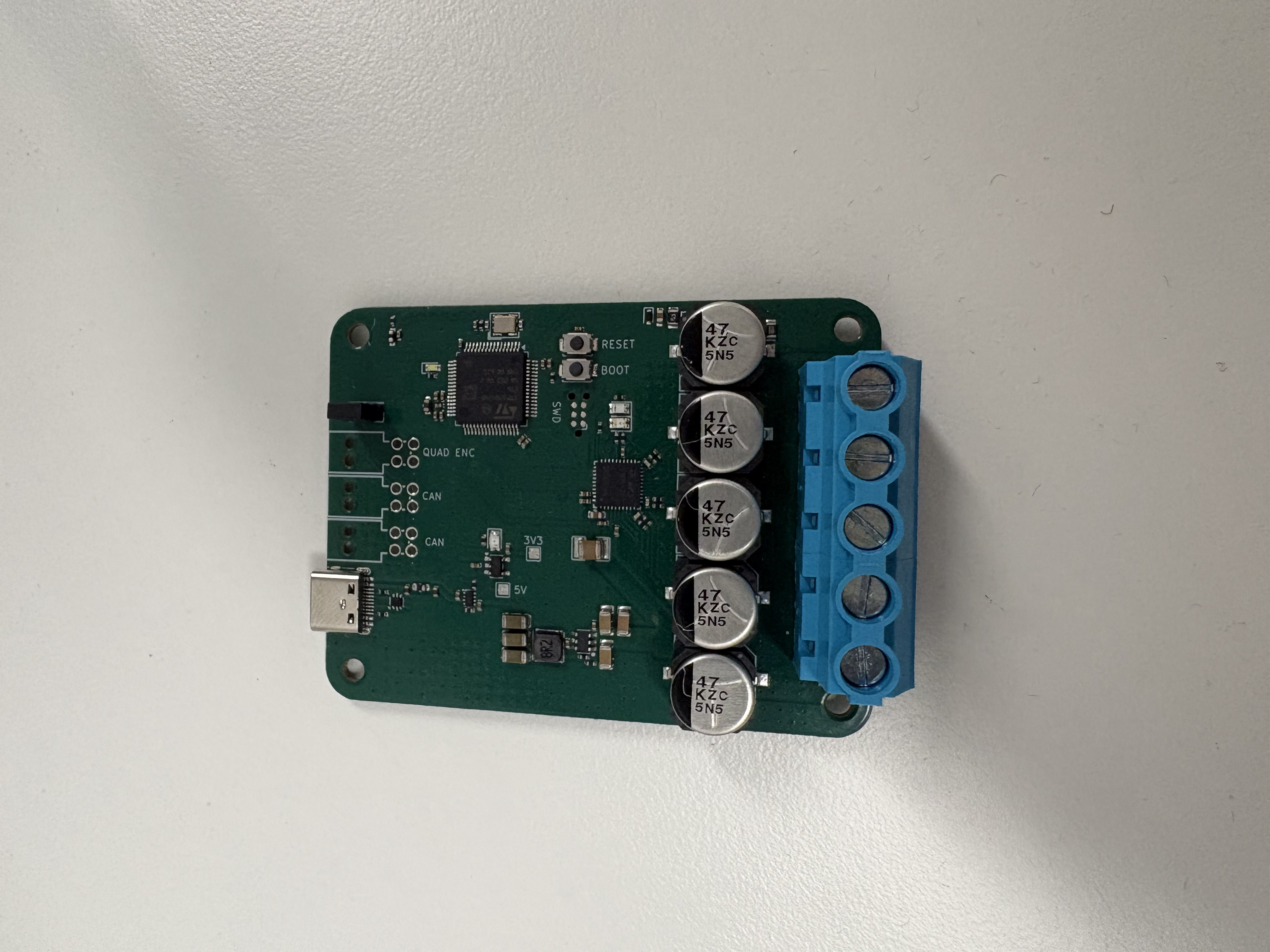
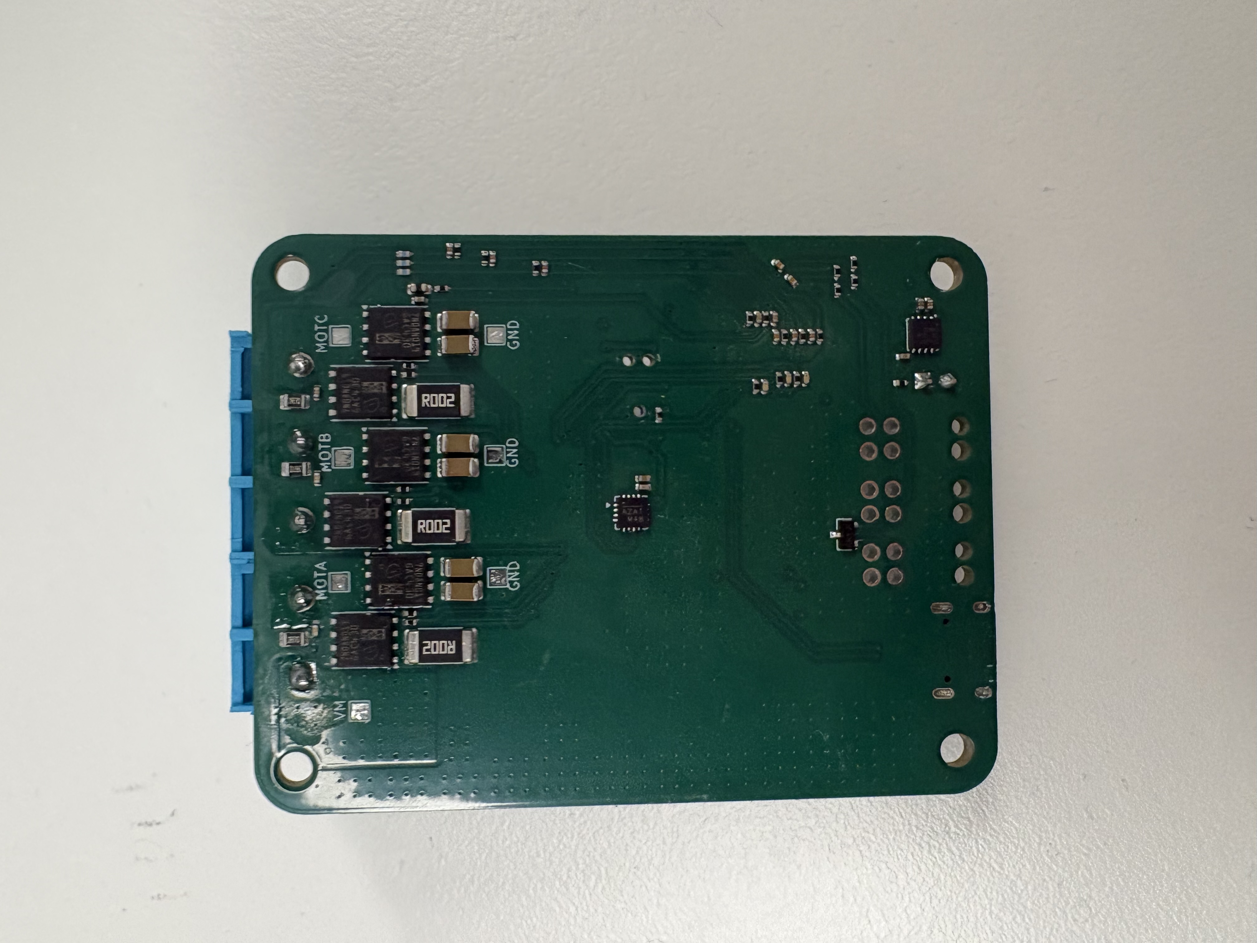
Bench stm32 esc is an open-source printed circuit board by JamesGossy, from the JamesGossy/STM32-Brushless-Motor-Controller repository on GitHub. It is a 4-layer board of 75 × 57 mm with 184 parts on 139 nets, routed with 752 tracks and 666 vias.
It is built around the TCAN1462VDRBRQ1, DRV8353SRTAR and AP2112K-3.3, with the TPD1E05U06DYAR, USBLC6-2P6 and IAUCN08S7N019ATMA1 among its other parts. Its parts include 73 capacitors, 56 resistors, 9 ICs, 7 connectors and 6 transistors. It belongs with the robots and motor control boards and the STM32 boards of this library.


A custom four-layer motor controller with bare-metal field-oriented control on an STM32G474. The project includes the PCB design, C firmware, a motor simulator and a live control dashboard.
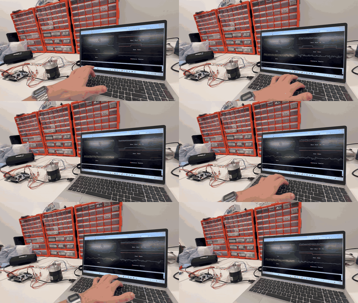
Real motor bench test with the live telemetry dashboard.
flowchart LR
    control["STM32G474<br/>Field-oriented control"]
    power["DRV8353S & MOSFETs<br/>Three-phase bridge"]
    motor["BLDC / PMSM motor"]
    control -->|PWM| power --> motor
    motor -->|Current & rotor position| control

    classDef controller fill:#eef2ff,stroke:#6366f1,color:#1e1b4b
    classDef drive fill:#ecfdf5,stroke:#059669,color:#064e3b
    class control controller
    class power,motor drive
| Item | Design |
|---|---|
| MCU | STM32G474RET6, 170 MHz |
| Gate driver | TI DRV8353S, configured over SPI |
| Input range | 12–60 V design target |
| Phase current | 25 A continuous design target; firmware defaults to a 20 A limit |
| MOSFETs | Six IAUCN08S7N019ATMA1, 80 V |
| Current sensing | Three 2 mΩ shunts with Kelvin connections |
| Position feedback | MA730 SPI encoder; external quadrature interface |
| PWM | HRTIM, 20 kHz, 200 ns dead time |
| Interfaces | CAN, USB CDC, UART and SWD |
| PCB | 57 × 75 mm, four layers |
The layout keeps gate-drive loops short, separates current-sense connections from power routing, and uses copper pours and via arrays to distribute current and heat. KiCad sources and manufacturing files are in controller_hardware/.
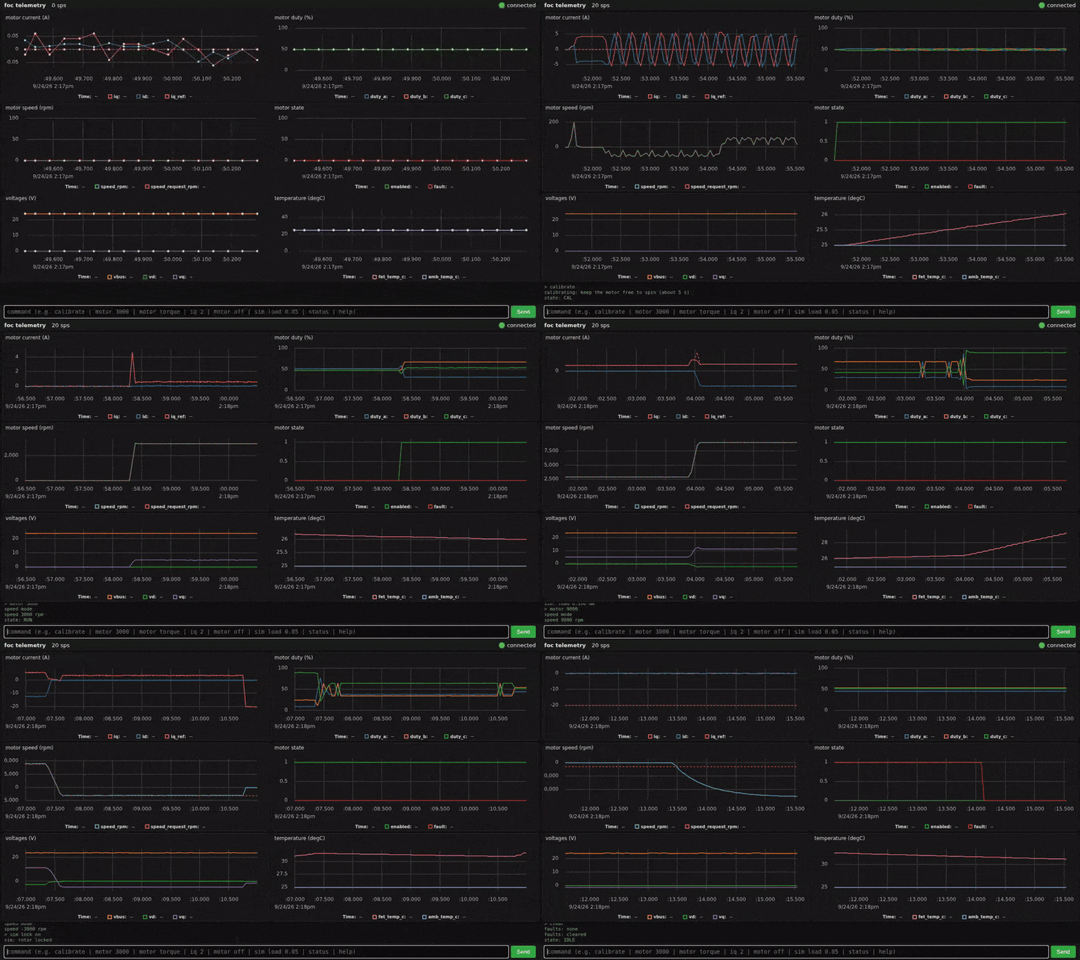
The dashboard connects to either the simulator or a board over USB. It shows motor telemetry and accepts commands for speed, torque, calibration and fault handling. The GIF above shows the simulator.
On Windows, run controller_firmware\tools\setup.bat to install missing tools, build the simulator and run tests. Then run controller_firmware\tools\dashboard.bat to open the dashboard.
For a manual build, install CMake, Ninja, a host C compiler and Python:
cd controller_firmware
cmake --preset sim
cmake --build --preset sim
ctest --preset sim
python -m pip install -r tools/dashboard/requirements.txt
python tools/dashboard/plot_motor.py --sim
Open localhost:8988. In the dashboard console, run calibrate, then motor 3000 to request 3,000 rpm. Use motor off to stop. Simulator commands such as sim load 0.1 and sim lock on exercise load response and fault handling.
Install STM32CubeCLT and put its Arm compiler, CMake, Ninja and STM32 programmer on PATH. From controller_firmware/:
cmake --preset default
cmake --build --preset default
cmake --build build --target flash
Flashing uses ST-Link over SWD. To connect the dashboard to the board:
python tools/dashboard/plot_motor.py --serial COM5Set the motor parameters and limits in app/config.h before running hardware. Start with a current-limited supply and an unloaded motor, then run calibration before requesting motion.
C tests cover control maths, SVPWM, configuration, commands and telemetry. Software-in-the-loop tests exercise calibration, torque and speed response, field weakening, CAN control and fault handling. CI builds the firmware and runs simulator and dashboard tests on Linux and Windows.
The electrical ratings above are design targets; simulation does not establish continuous-current capability or thermal performance. This board revision has no on-board reverse-polarity protection, fuse or bus TVS.
| Location | Contents |
|---|---|
controller_hardware/ | KiCad schematics, PCB layout and manufacturing files |
controller_firmware/app/ | FOC, control loops, calibration, commands and telemetry |
controller_firmware/hal/stm32g474/ | HRTIM, ADC, encoder, gate-driver, CAN and USB drivers |
controller_firmware/sim/ | Simulated hardware interface, motor model and TCP server |
controller_firmware/tests/ | Unit and motor simulation tests |
controller_firmware/tools/dashboard/ | Browser dashboard and Python bridge |
MIT licensed. Copyright © 2026 James Goss.
| Qty | Value | Footprint | References |
|---|---|---|---|
| 20 | 100nF | PCM_JLCPCB:C_0402 | C5, C11, C12, C20, C22, C30, C31, C33, C41, C46, C47, C48, C49, C50, C53, C64 +4 |
| 11 | 1uF | PCM_JLCPCB:C_0402 | C13, C14, C15, C29, C36, C37, C42, C43, C45, C52, C93 |
| 10 | 100Ω | PCM_JLCPCB:R_0402 | R1, R2, R42, R44, R45, R46, R47, R48, R49, R56 |
| 9 | TestPoint | TestPoint:TestPoint_Pad_1.5x1.5mm | TP1, TP6, TP7, TP8, TP9, TP10, TP11, TP12, TP13 |
| 6 | 10Ω | PCM_JLCPCB:R_0402 | R25, R26, R27, R28, R31, R32 |
| 6 | 1nF | PCM_JLCPCB:C_0402 | C21, C24, C25, C51, C66, C67 |
| 6 | 4.7uF | PCM_JLCPCB:C_1206 | C68, C69, C70, C71, C72, C73 |
| 6 | IAUCN08S7N019ATMA1 | Package_TO_SOT_SMD:TDSON-8-1 | Q1, Q2, Q3, Q4, Q5, Q6 |
| 6 | NetTie_2 | NetTie:NetTie-2_SMD_Pad0.5mm | NT1, NT2, NT3, NT4, NT5, NT6 |
| 5 | 10kΩ | PCM_JLCPCB:R_0402 | R22, R24, R43, R50, R53 |
| 5 | 2.2nF | PCM_JLCPCB:C_0402 | C18, C26, C32, C39, C40 |
| 5 | EEHZC1K470V | easyeda2kicad:CAP-SMD_BD10.0-L10.3-W10.3-FD | C1, C2, C3, C4, C7 |
| 4 | 1kΩ | PCM_JLCPCB:R_0402 | R34, R36, R41, R55 |
| 4 | MountingHole | MountingHole:MountingHole_3.2mm_M3 | H1, H2, H3, H4 |
| 3 | 100kΩ | PCM_JLCPCB:R_0402 | R6, R23, R51 |
| 3 | 1053141104 | easyeda2kicad:CONN-TH_4P-P2.50_MOLEX_1053141104 | CN1, CN2, CN3 |
| 3 | 10nF | PCM_JLCPCB:C_0402 | C56, C57, C58 |
| 3 | 1uF | PCM_JLCPCB:C_1206 | C23, C27, C28 |
| 3 | 2.7Ω | PCM_JLCPCB:R_0805 | R7, R10, R13 |
| 3 | 2mΩ | Resistor_SMD:R_2512_6332Metric | R8, R9, R12 |
| 3 | 330Ω | PCM_JLCPCB:R_0402 | R3, R4, R5 |
| 3 | 383kΩ | PCM_JLCPCB:R_0402 | R33, R35, R37 |
| 3 | 47nF | PCM_JLCPCB:C_0402 | C61, C62, C63 |
| 3 | 47uF | PCM_JLCPCB:C_1206 | C10, C17, C19 |
| 3 | 56Ω | PCM_JLCPCB:R_0402 | R15, R16, R20 |
| 3 | 9.76kΩ | PCM_JLCPCB:R_0402 | R38, R39, R40 |
| 2 | 18pF | PCM_JLCPCB:C_0402 | C85, C87 |
| 2 | 2.2uF | PCM_JLCPCB:C_0402 | C54, C55 |
| 2 | 20kΩ | PCM_JLCPCB:R_0402 | R52, R54 |
| 2 | 4.7kΩ | PCM_JLCPCB:R_0402 | R17, R21 |
| 2 | 47nF | PCM_JLCPCB:C_0603 | C6, C38 |
| 2 | 5.1kΩ | PCM_JLCPCB:R_0402 | R29, R30 |
| 2 | Tactile Button, 160gf | PCM_JLCPCB:SW_TS-1088-AR02016 | S1, S2 |
| 2 | Thermistor_NTC | PCM_JLCPCB:R_0603 | TH1, TH2 |
| 2 | ~ | PCM_JLCPCB:FB_0603 | FB1, FB2 |
| 1 | 120Ω | PCM_JLCPCB:R_0402 | R14 |
| 1 | 19.1kΩ | PCM_JLCPCB:R_0402 | R11 |
| 1 | 383kΩ | PCM_JLCPCB:R_0805 | R18 |
| 1 | 4.7uF | PCM_JLCPCB:C_0402 | C44 |
| 1 | 9.76kΩ | PCM_JLCPCB:R_0805 | R19 |
| 1 | AP2112K-3.3 | Package_TO_SOT_SMD:SOT-23-5 | U6 |
| 1 | Conn_02x01 | Connector_PinHeader_2.54mm:PinHeader_2x01_P2.54mm_Vertical | J1 |
| 1 | Conn_ARM_SWD_TagConnect_TC2030-NL | Connector:Tag-Connect_TC2030-IDC-NL_2x03_P1.27mm_Vertical | J3 |
| 1 | DRV8353SRTAR | easyeda2kicad:WQFN-40_L6.0-W6.0-P0.50-TL-EP4.5 | U4 |
| 1 | FNR4020S8R2MT | easyeda2kicad:IND-SMD_L4.0-W4.0_FNR40XXS | L1 |
| 1 | GRM32EC72A106KE05L | easyeda2kicad:C1210 | C9 |
| 1 | Green | PCM_JLCPCB:D_0805 | D2 |
| 1 | LM66200DRLR | easyeda2kicad:SOT-583-8_L2.1-W1.2-P0.50-LS1.6-BL | U5 |
| 1 | LMR51635YDDCR | easyeda2kicad:SOT-23-6_L2.9-W1.6-P0.95-LS2.8-BL | U1 |
| 1 | MA730 | Package_DFN_QFN:QFN-16-1EP_3x3mm_P0.5mm_EP1.75x1.75mm | U2 |
| 1 | NetTie_2 | NetTie:NetTie-2_SMD_Pad2.0mm | NT7 |
| 1 | PESD2CAN,215 | easyeda2kicad:SOT-23-3_L2.9-W1.3-P1.90-LS2.4-BR | D3 |
| 1 | Red | PCM_JLCPCB:D_0805 | D4 |
| 1 | STM32G474RETx | Package_QFP:LQFP-64_10x10mm_P0.5mm | U7 |
| 1 | Screw_Terminal_01x05 | footprints:CUI_TB005_-762-05BE | J4 |
| 1 | TCAN1462VDRBRQ1 | easyeda2kicad:DFN-8_L3.0-W3.0-P0.65-TL-EP2.4 | U8 |
| 1 | TPD1E05U06DYA | PCM_JLCPCB:D_SOD-523 | U3 |
| 1 | USBLC6-2P6 | Package_TO_SOT_SMD:SOT-666 | U20 |
| 1 | USB_C_Receptacle_USB2.0_16P | Connector_USB:USB_C_Receptacle_HRO_TYPE-C-31-M-12 | J2 |
| 1 | White | PCM_JLCPCB:D_0603 | D1 |
| 1 | X322524MOB4SI | easyeda2kicad:CRYSTAL-SMD_4P-L3.2-W2.5-BL | X1 |
| 1 | Yellow | PCM_JLCPCB:D_0805 | D6 |

sujaygouda123/foc-control
BLDC field-oriented-control board for a humanoid robot actuator. KiCad 10, Ø80 mm, 8 layers, 1.6 mm.

EPFLRocketTeam/2026_C_AV_HARDWARE
Repository containing PCBs files of FH2 Avionics

lukatrisic/MPPT-Controller
Full MPPT Controller with schematics, PCB layout and code


iamdarshg/drone-arm
Reworked cheaper, maybe faster but less redundant drone controller.

darshp848/bldc-controller-60v
60 V, 20 A / 80 A peak BLDC motor controller that fits the MD80 v3.0 mounting. KiCad 10, 6 layers.
It measures 75 × 57 mm and has 4 copper layers, 1.66 mm thick.
184 parts, built around the TCAN1462VDRBRQ1, DRV8353SRTAR, AP2112K-3.3 and TPD1E05U06DYAR. The full list of its parts is on this page, with links to each part's symbol and footprint where PCBKit's library has them.
From the JamesGossy/STM32-Brushless-Motor-Controller repository on GitHub, at the commit this page was made from: the board is controller_hardware/bench_stm32_esc.kicad_pcb and its schematic controller_hardware/bench_stm32_esc.kicad_sch. PCBKit opens the board in the browser, with nothing to install.
Its repository states no licence, so its author keeps all rights: ask JamesGossy before reusing the design.