
2 layers
 timdeegan/flicker3
Lighting flicker meter
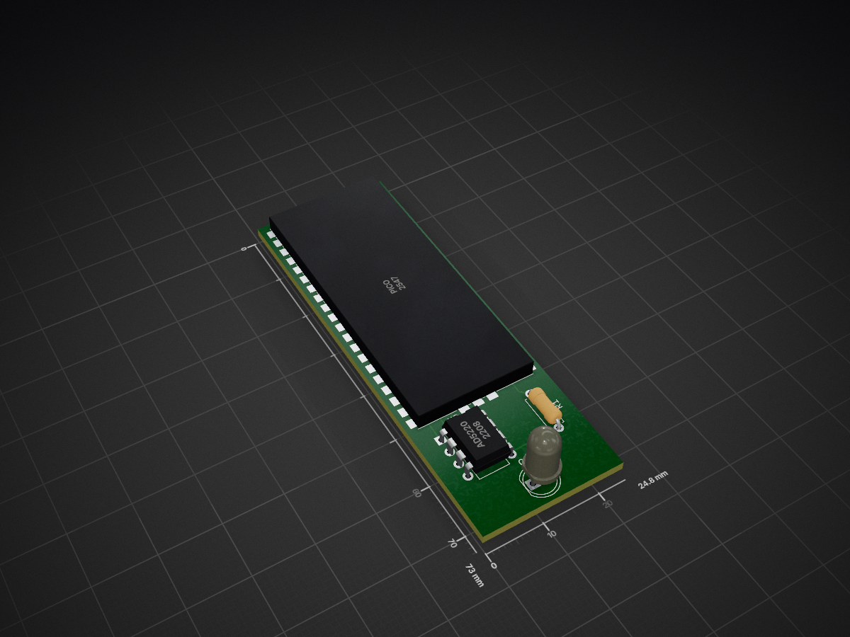
Flicker is an open-source printed circuit board by timdeegan, from the timdeegan/flicker repository on GitHub. It is a 2-layer board of 24.8 × 73 mm with 4 parts on 45 nets, routed with 27 tracks and 0 vias.
It is built around the AD522-00E and SFH 300. Its parts include 2 ICs, 1 resistor and 1 transistor. It belongs with the lEDs and displays boards and the RP2040 boards of this library.
This device measures the amount and speed of flicker in light sources and screens, using a phototransistor to measure the light and a Raspberry Pi Pico for signal processing. It was designed to be cheap (less than £10 for parts in bulk, probably more like £30 to build just one) while still accurate enough to evaluate screens and lighting for those who are sensitive to flickering light. (For information about the effects of flickering light, see e.g. Lehman and Wilkins, 2014.)
The PCB is a simple 2-layer layout, easily within the cheapest tier of JLCPCB or other manufacturers. The KiCAD files are in the pcb directory, along with all the output files needed to order your own PCBs.
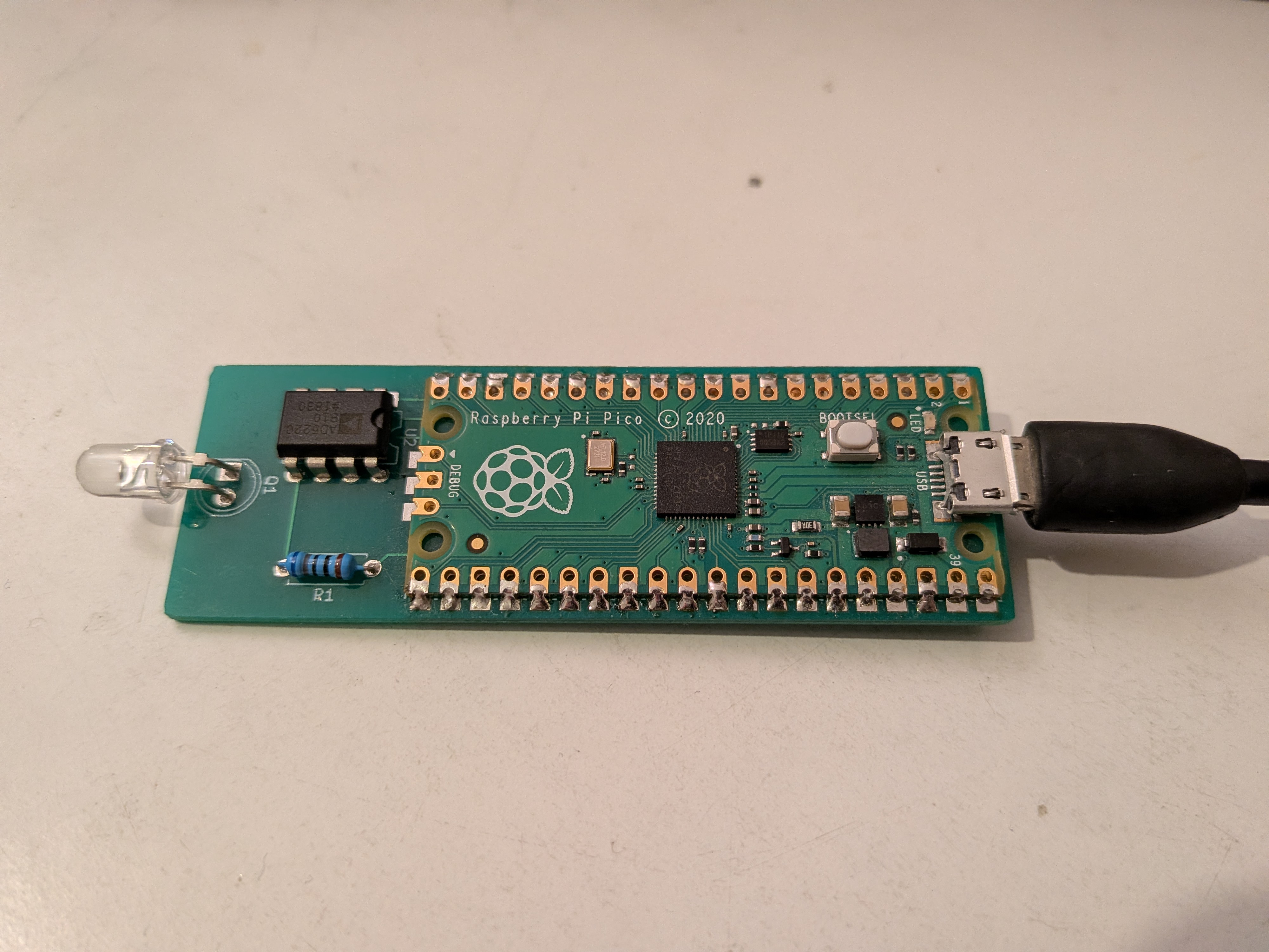
There are only four things to solder on:
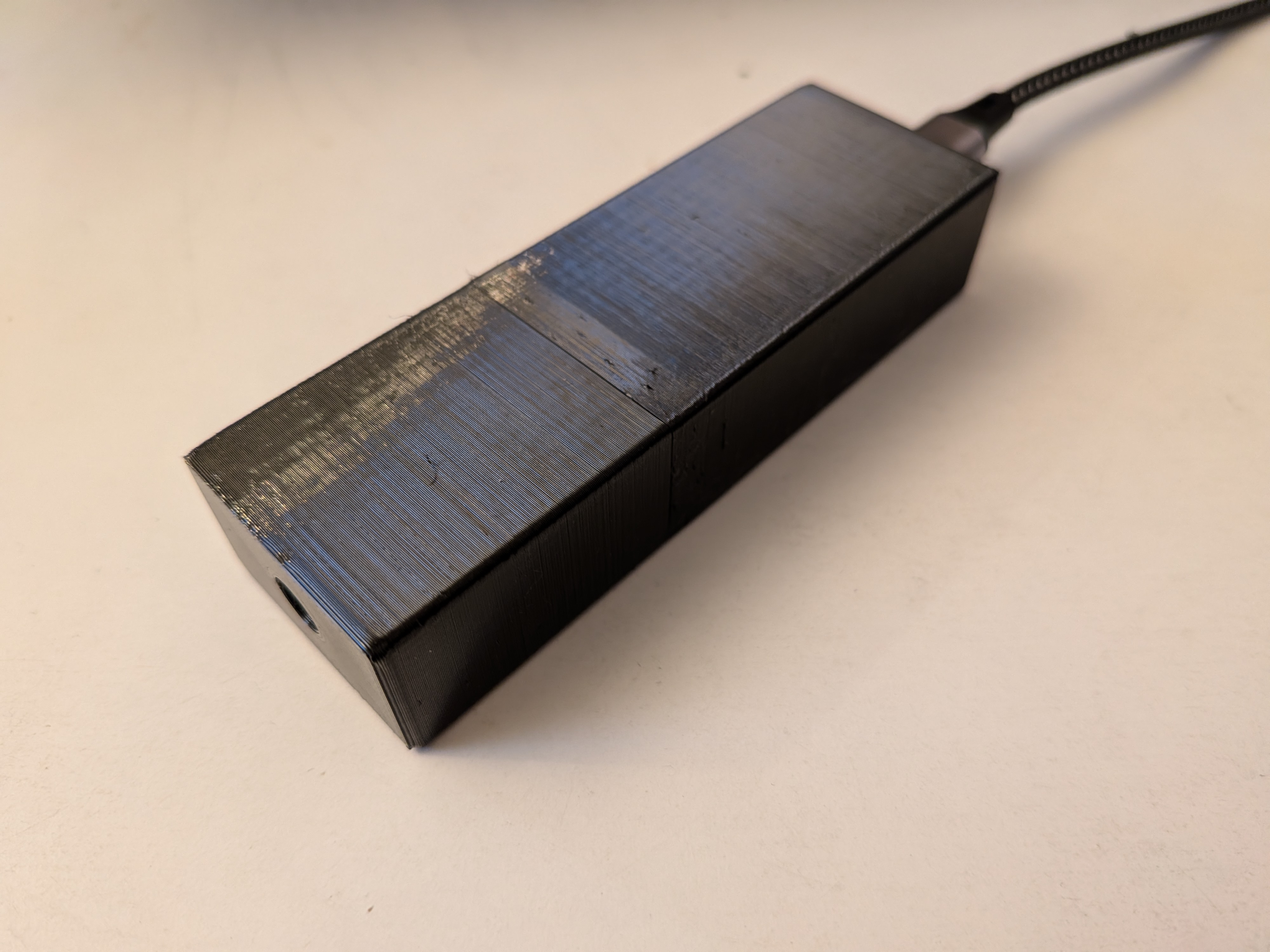
The 3D model for the case is in case/case.3mf. I printed mine in PETG at 0.15mm "quality" on a Prusa i3 MK3S printer.
The firmware that runs on the Pico is in firmware/flicker-v1.0.uf2.
First connect the board by USB while holding the BOOTSEL button, which makes it appear as a USB-attached drive. Then copy the .uf2 file to that drive.
The firmware source is in the firmware directory. If you want to build it yourself, you will need the Raspberry Pi Pico SDK. Once you have the SDK installed, you should be able to build the firmware using the Visual Studio Code extension as documented in the SDK.
The flicker meter appears as a USB serial device.
Point the sensor at the light you want to measure. It's usualy best to get quite close to the light it you can, unless you see a warning about it being too bright. The measurements appear on the serial output, along with graphs of the frequency and waveform. The graphs work best with a monospaced font and a window at least 80 characters wide.
E.g. measuring a CFL lightbulb:
AGC: 66/127
--------------------------------------------------------------------------------
                  *
                 * *
                 * *
                 * *
                *  *
                *   *
                *   *
                *   *
               *    *
               *    *
               *    *
              *      *
              *      *
              *      *
              *      *  *
********     *       *  ***
*       *    *        * * *
*        ****         * * * *
                       *  ** * ***                                             *
                           * ** ************************************************
--------------------------------------------------------------------------------
FFT: peak at 100.105042HzThe important numbers there are 10% flicker (the amount by which the brightness varies over one cycle of the flickering) and 100Hz (how fast it is flickering, in this case twice the 50Hz mains electricity frequency).
By contrast, a mobile phone screen using PWM for brightness control shows a faster but much deeper flicker:
AGC: 127/127 (TOO DARK)
--------------------------------------------------------------------------------
                          *
                          *
                          *
                          **     *
                          **     *
                          **     *
                          **     *   *
                         * *    **   *
                         * *    **   *
                         * *    **  **
                         * *    **  ** *
                         * *    **  ** **
                         * *    **  ** **
                         * *    **  ** **
                         * *    **  ** ****
                        *  *    **  ** ****
                        *   *   **  ** ****
                        *   *   * * ** *****
         ************   *   *   * * *  *** *  ****                             *
*********            ****    ****  ***** ***************************************
--------------------------------------------------------------------------------
FFT: peak at 239.751190HzIt doesn't handle very bright or very dark sources, though it will warn about them being too bright or dark. It tends to report flicker of >60KHz when in total darkness, which I assume is noise from the Pi Pico.
The phototransistor circuit is rather simple, based on my limited knowledge at the time, and the brightness compensation is a bit clunky. I would like to redesign it at some point with a proper variable-gain amplifier and an antialiasing filter.
I haven't tried calibrating this meter or comparing it to a properly calibrated one. Calibrated meters are rather expensive, which is why I built this in the first place. If you have access to proper calibration equpment and would like to test one of these meters, get in touch!
It measures 24.8 × 73 mm and has 2 copper layers, 1.6 mm thick.
4 parts, built around the AD522-00E and SFH 300. The full list of its parts is on this page, with links to each part's symbol and footprint where PCBKit's library has them.
From the timdeegan/flicker repository on GitHub, at the commit this page was made from: the board is pcb/flicker.kicad_pcb and its schematic pcb/flicker.kicad_sch. PCBKit opens the board in the browser, with nothing to install.
Its repository states no licence, so its author keeps all rights: ask timdeegan before reusing the design.


AgustinPrietoValdez/competition-robots
Custom competition robots — maze/micromouse (MISA), sumo (TATAMI 1) & mini-sumo (RUCHO). KiCad PCBs, STM32/Arduino firmware, Fusion 360. National champion & international prizes — by EDNAROBOTICS.

joypad-ai/joypad-os
Universal controller firmware for building adapters, dongles, and custom controllers.


hackclub/OnBoard
💡 Join 1,000 teenagers and make your first PCB with a $100 grant!

tardate/LittleArduinoProjects
a collection of "Little Electronic & Arduino Projects", most involving electronics or an Arduino in one way or another!

drandyhaas/KiCadRoutingTools
A set of Python/Rust tools to aid routing in KiCad