2 layers304.8 × 95.3 mm

 thpoll83/PolyKybd411
PolyKybd
Poly kb is an open-source printed circuit board by thpoll83, from the thpoll83/PolyKybd repository on GitHub, published under the CERN-OHL-W-2.0 licence. It is a 2-layer board of 116.8 × 86.4 mm with 161 parts on 173 nets, routed with 4,076 tracks and 390 vias.
It is built around the 74HCT595D, USBLC6-2SC6 and XC6206P332MR, with the WS2812B-MINI-X2 among its other parts. Its parts include 69 capacitors, 43 connectors, 17 resistors, 5 ICs and 4 diodes. It belongs with the keyboards and input and lEDs and displays boards and the STM32 boards of this library.


Official hardware repository of the PolyKybd Split72 keyboard. If you are looking for the kit, jump immediately to https://www.crowdsupply.com/polykybd/polykybd for registration.
The instructions here are still in a very early stage. There is also a build video available: https://www.youtube.com/watch?v=K5RpbYzx7gw
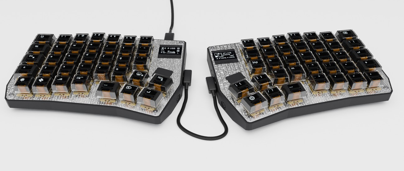
You can find the matching QMK firmware here: https://github.com/thpoll83/qmk_firmware/tree/PolyKybd
This repo is big — around 800 MB of history. Most of that is the board files themselves: the
decorative silkscreen artwork is stored as vector polygons, which makes a single .kicad_pcb
around 50 MB, and there are several design generations in the history.
If you just want the current files, use a partial clone. Git then downloads file contents only when you actually touch them, so a fresh checkout takes seconds instead of many minutes:
git clone --filter=blob:none https://github.com/thpoll83/PolyKybd.gitThe full history is still there and everything works normally — git log, git checkout, opening
the boards in KiCad. Older revisions of large files are simply fetched on demand. If you want a
plain full clone instead, just leave the --filter off.
The PCB projects are the following (KiCad 9 — the schematics were migrated to the version 9 file format, so KiCad 8 and earlier can no longer open them):
poly_kybd/poly_kybd_split72_right.kicad_pro poly_kybd/poly_kybd_split72_left.kicad_pro
(please just use the projects linked above and ignore any older/backup projects in the folder)
Here are the corresponding schematics for reference (left and right):
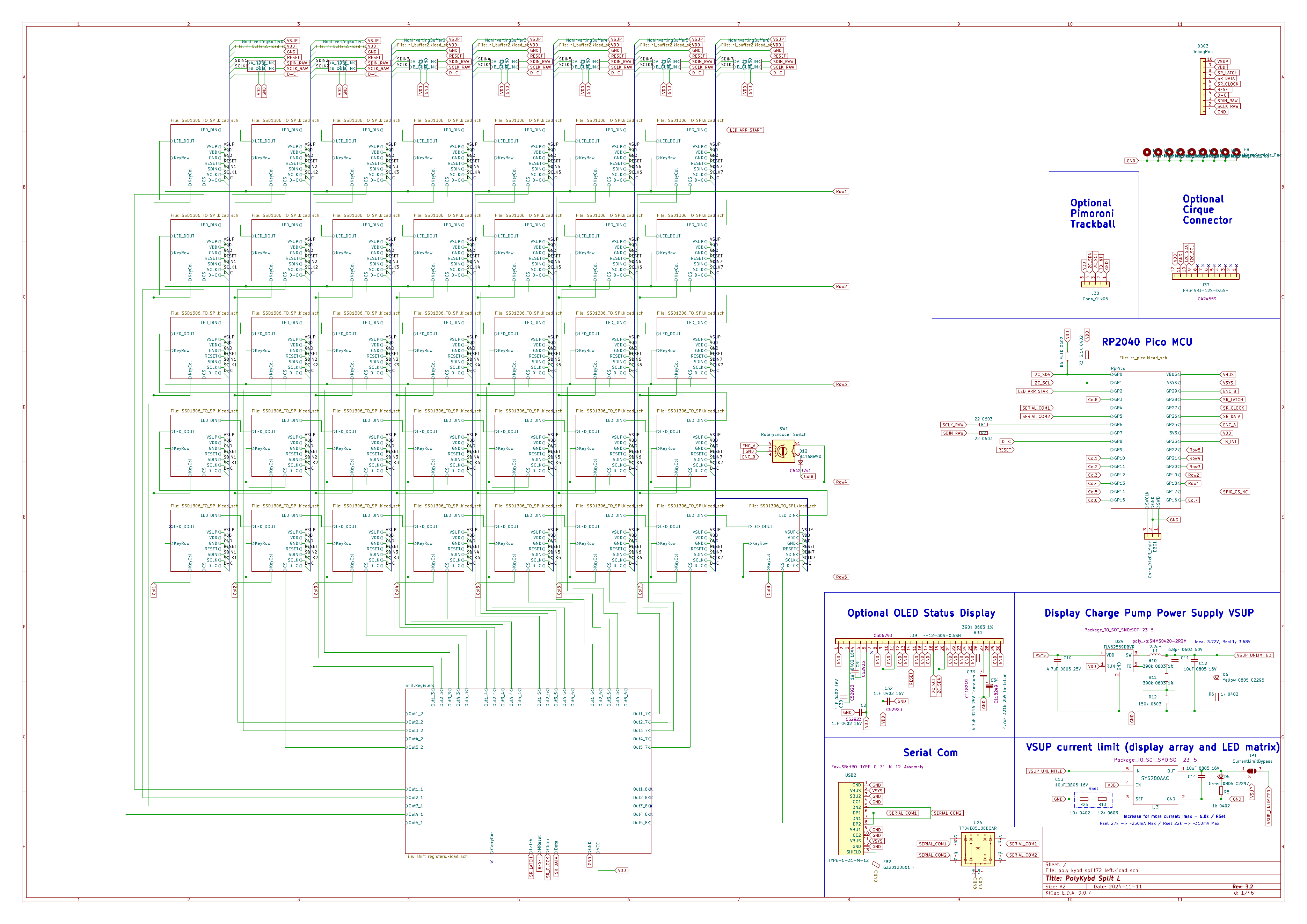
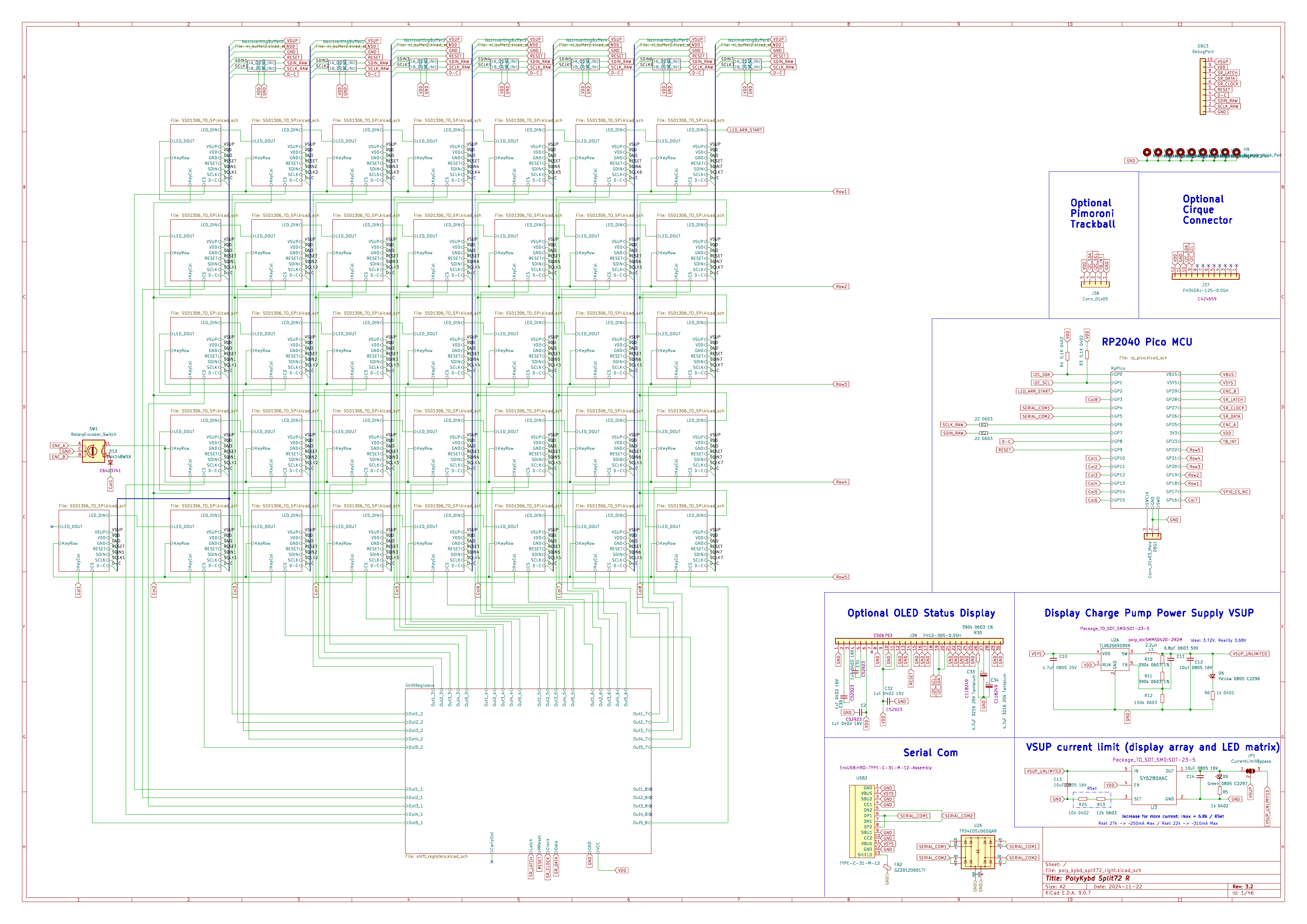
You can inspect all individual schematic sheets (with descriptions) here: Schematic sheets.
The keyboard plates are also KiCad projects, still in an older file format but they open fine in KiCad 9 (I used 1.2mm aluminum PCBs):
poly_kybd/poly_kybd_split72_plate_right.kicad_pro poly_kybd/poly_kybd_split72_plate_left.kicad_pro
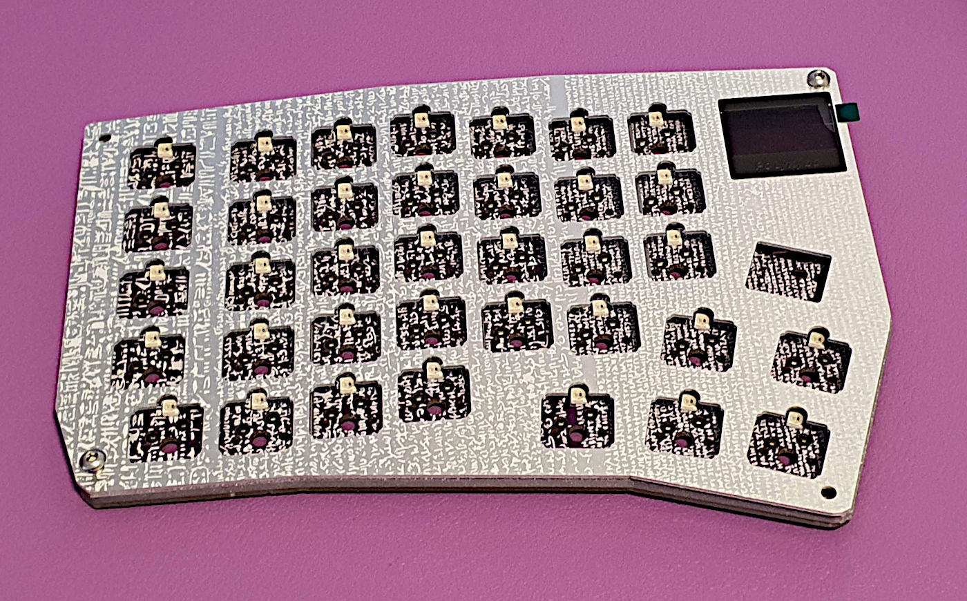
I recommend waiting for the kit that contains all parts and the assembled PCBs. Here a little preview, how that looks like:
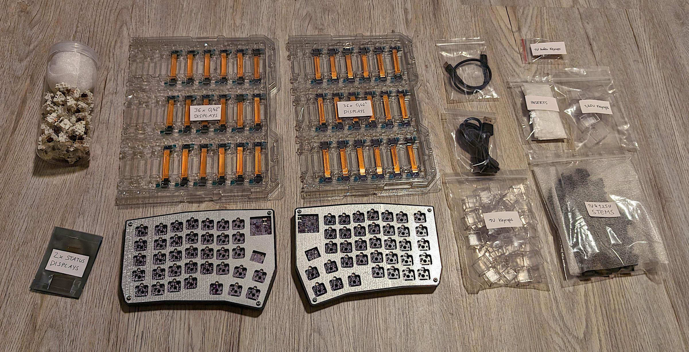 The kits are not yet ready, but you can sign up here and get notified as soon as these are available: https://www.crowdsupply.com/polykybd/polykybd
At the moment, please consider these instructions as experimental. If you want to go ahead with the full experience and build everything from scratch right now: Give it a try and let me know how it worked out!
Independent of your choice, here are the parts you need before putting everything together:
Case (left/right) - You can either 3D print or get them CNCed (but then you should add some threads to the screw holes):
parts/export/case/case_polykybd_split72_left_r7.stl
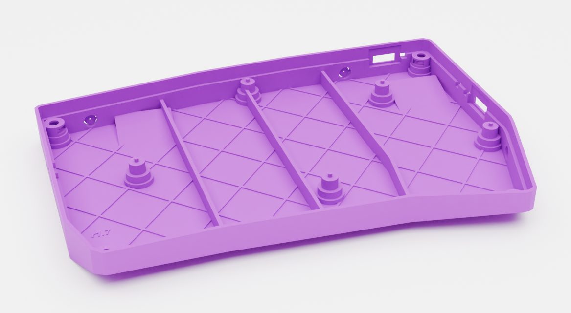 parts/export/case/case_polykybd_split72_right_r7.stl
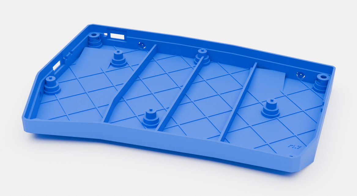 In case the resin print has some deformations, it is best to use a hairdryer to slightly heat the case up and then put something heavy on the bottom to make it flat - it really works.
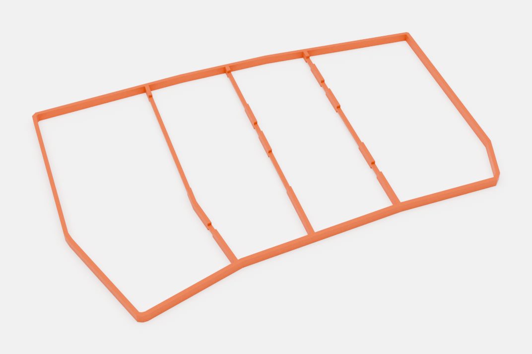
Spacer to keep the right distance between plate and PCB (again, can be 3D printed):
parts/export/case/spacer.stl. If you fit the LED diffuser frame, print parts/export/case/spacer_diffuser_frame.stl instead. It is notched for the frame on both faces, so one part works on either half.
Assembled 4 layers PCB 1.6mm (left/right) The latest gerber files with BOM and pick/place file can be found in poly_kybd/Gerber I made some final adjusts on the latest version, which I did not yet order (I will let you know as soon as I did). poly_kybd/Gerber/PCB/left-side-v3.2/PolyKybd_Split72_L_3.2.zip poly_kybd/Gerber/PCB/right-side-v3.2/PolyKybd_Split72_R_3.2.zip
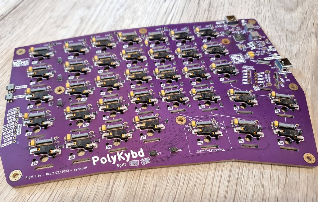
My recommendation is to let assemble the PCBs as there are a lot of parts with tiny footprints like the RP2040, the 72 FPC sockets and some more... If your PCB fab has an option to verify the parts orientation, please make use of it. I did that as well and never bothered correcting them (since the 'upright' orientation of the part from KiCad and your PCB fab might differ).
In case you make modifications to the PCB in KiCad and export everything you might need to change the hot swap sockets side to the back. The hot swap socket in KiCad is part of the key switch and for some reason I couldn't yet convince KiCad that the manufacturing side is the back...
Aluminum plates (left/right =) - Can be ordered from PCB manufactures as a 1.2mm aluminum PCB poly_kybd/Gerber/Plate/gerber-left-side-v3-17.11.2023.zip poly_kybd/Gerber/Plate/gerber-right-side-v3-17.11.2023.zip
Displays
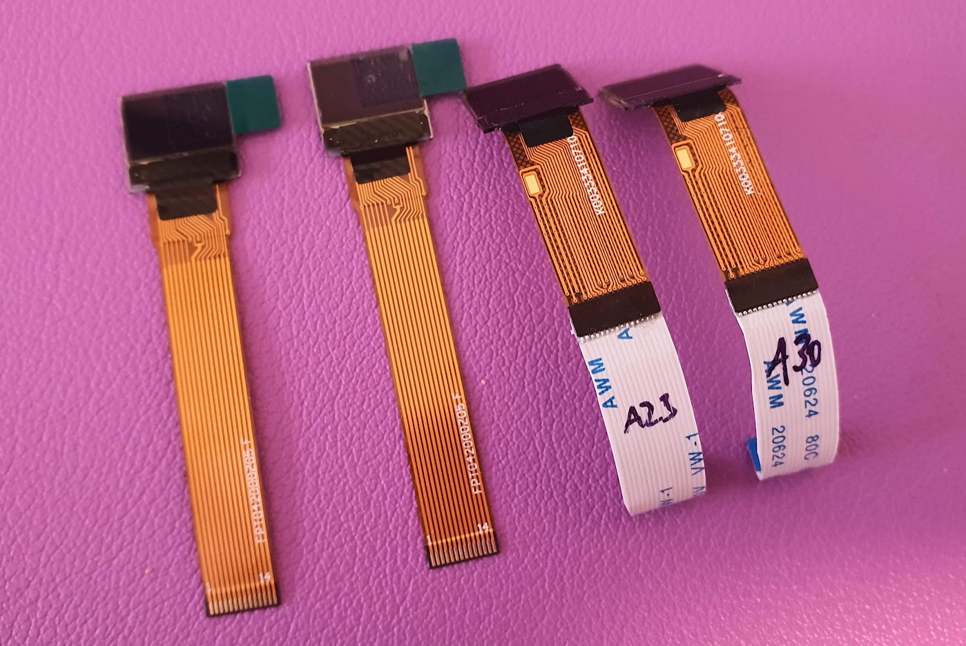
72 pieces 0.42 inch displays
(Optional) 2 pieces 0.96 inch status displays (FPW096W001Z0) or pin compatible (see below), the flex cable length should be about 40mm or you extend it on your own. You can contact this supplier: FET, they have these displays even they are not listed in their online catalogue.
| PIN | SIGNAL | PIN | SIGNAL |
|---|---|---|---|
| 1,30 | N/C (GND) | 14 | RES# |
| 2,3 | C2P,C2N | 15 | D/C# |
| 4,5 | C1P,C1N | 16 | R/W# |
| 6 | VDDB/VBAT | 17 | E/RD# |
| 7 | N/C | 18~25 | D0~D7 |
| 8 | VSS | 26 | IREF |
| 9 | VDD | 27 | VCOMH |
| 10~12 | BS0~BS2 | 28 | VCC |
| 13 | CS# | 29 | VLSS |
If you don't need the status displays, you can close the display cut-out with the dummy holder: Dummy Display Holder
MX Compatible key switches (3 or 5 pins) - 72 pieces. From my blog post ( https://ko-fi.com/post/More-Key-Switch-Testing-While-Waiting-For-The-Asse-B0B8HX1HW ), you can find out, that there are 2 categories of compatible key switches. The ones that work out of the box and the ones that need a little modification. Basically all switches that have an LED slit that is at least 7.5mm wide work. I tested quite some switches and here is the list of tested switches that will work for sure without modification:
| SWITCH | TYPE | MISC |
|---|---|---|
| Aflion Tropical Waters | Linear | 68g |
| Ashkeebs Alexandrite | Linear | 58g |
| Blue Dusk Panda | Linear | 62g |
| BSUN x Unikeys Udon | Linear | 48g |
| CK x Haimu Pastel Lemon | Linear | 63.5g |
| Ck x Haimu Pastel Thistle | Tactile | 63.5g |
| Gateron KS-9 (Pro) Blue | Clicky | 60g |
| Gateron KS-9 (Pro) Brown | Tactile | 55g |
| Gateron KS-9 (Pro) Green | Clicky | 80g |
| Gateron KS-9 (Pro) Red | Linear | 45g |
| Gateron KS-9 (Pro) Yellow | Linear | 50g |
| Geon Black | Tactile | 60g |
| Geon Clear | Linear | 60g |
| Geon Yellow | Linear | 63.5g |
| Glorious Panda | Tactile | 67g |
| GOJU Works x Tecsee Safety Switch | Linear | 65g |
| HMX Cthulhu | Linear | 45-50g |
| HMX Emo | Linear | 40g |
| HMX Hazelnut V2 | Linear | 43g |
| HMX K01 Light | Tactile | 45g |
| HMX Lotus | Linear | 62.5g |
| HMX Su Color Pink | Linear | 45g |
| HMX x Sillyworks Sonja | Linear | 45g |
| HMX x Unikeys Purple Dawn | Linear | 55g |
| Kailh Novel Keys Cream Switch | Linear | 55g |
| Kailh Purple Potato | Tactile | 63.5g |
| Kailh x Domikey Knight Saber | Tactile | 42g |
| Keygeek M3 | Linear | 48g |
| LCET Grace | Linear | 50g |
| LCET Joker | Tactile | 58g |
| LCET Pink Queen | Tactile | 58g |
| LCET Sprout | Linear | 50g |
| MMD Holy Panda V3 | Tactile | 45g |
| Outemu (Dustproof) Black | Linear | 65g |
| Outemu (Dustproof) Blue | Clicky | 65g |
| Outemu (Dustproof) Brown | Tactile | 50g |
| Outemu (Dustproof) Red | Linear | 46g |
| Outemu Crystal Clear | Linear | 45g |
| Outemu Dust-proof Silver | Linear | 45g |
| Outemu Lemon | Silent Tactile | 35g |
| Outemu Panda | Tactile | 50g |
| Outemu Peach | Linear | 40g |
| Outemu Purple | Tactile | 45g |
| Outemu Ocean | Linear | 35g |
| Outemu Teal | Clicky | 70g |
| Owlab Neon | Linear | 62g |
| Tecsee Medium (low profile) | Linear & Tactile | 50g |
Be aware that there are different batches of Gateron KS-9 (with and without 'Pro') switches. Despite the exact same name, they might need the following surgery (better ask before buy). So, some switches have an LED slit, but with a little plastic bar in the middle:
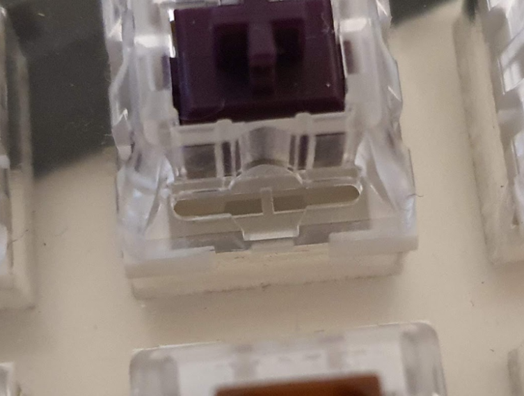
You can simply cut it away with a knife:
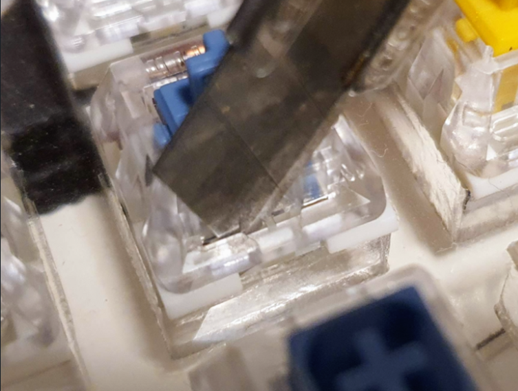
It is not a big deal, just consider it. Here is a list of switches that I successfully tested after this little modification:
| SWITCH | TYPE | MISC |
|---|---|---|
| Gateron KS-9 (Pro 2.0) Red | Linear | 45g |
| Gateron KS-9 (Pro 2.0) White | Linear | 35g |
| Geon HG [Haimu x Geon] Black | Linear | 65g |
| Geon HG [Haimu x Geon] White | Tactile | 65g |
| Geon HG [Haimu x Geon] Red | Silent Linear | 65g |
| Geon HG [Haimu x Geon] Yellow | Silent Tactile | 65g |
| Kailh BOX V2 Red Switch | Linear | 40g |
| Kailh Box Cream | Linear | 45g |
| Kailh Pro Purple | Tactile | 50g |
| Kailh Pro Burgundy | Linear | 50g |
| Kailh Pro Light Green | Clicky | 50g |
| Kailh Pro Plum | Tactile | 70g |
| Kailh Speed Gold | Clicky | 50g |
| Kailh Speed Silver | Linear | 50g |
| Kailh Speed Bronze | Clicky | 50g |
| Kailh Speed Copper | Tactile | 40g |
| Kailh Speed Burnt Orange | Linear/Tactile | 70g |
| Kailh Speed Pro Heavy Army Green | Clicky | 70g |
| Kailh Speed Pro Heavy Yellow | Linear | 70g |
| Kailh Black | Linear | 60g |
| Kailh RGB Red | Linear | 45g |
| Kailh RGB Black | Linear | 60g |
| Kailh RGB Blue | Clicky | 50g |
| Kailh RGB Brown | Tactile | 50g |
There are many more switches that will work as long as they have a 7.5mm wide LED slit. Let me know in case you successfully tried another switch, then I can update the list.
Key Stems - 72 pieces, can be 3D printed (I highly recommend using an SLA printer). There are 3 different profiles available here. You can also modify the source file an make your own profile. If you take the STLs, make sure to always grab the latest version.
Every plate is in parts/export/keycap_stem/, named
keycap_stem_revAlpha_<width>_<profile>_10p.stl — where width is 1U or
1U25 (not 1.25U) and profile is one of R1–R5, S1, S, S5, e.g.
keycap_stem_revAlpha_1U25_R1_10p.stl. Ten pieces per plate, so divide the
counts below by ten (rounding up) to know how many of each to print.
Every piece carries its profile and revision engraved on the top face
(R5 α, S1 α, …), matching the profile token in the filename — so a printed
stem can always be traced back to the plate that made it, and a mixed handful
can be sorted back out.
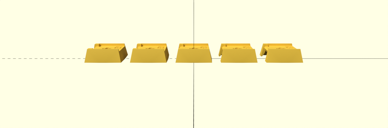 One stem for every row: the
R3 plates (14 pieces 1.25U and 58 pieces 1U).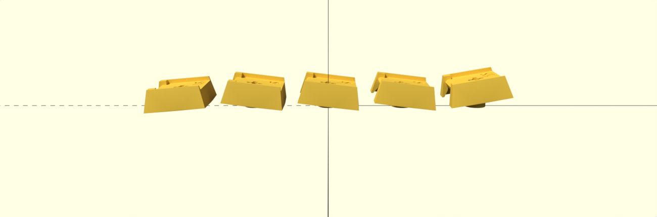 Rows tilted rather than curved. This works best if the keyboard is inclined by 5 degrees or more, and comes in two variations:
S1 on the front row, S5 on the back row, S on the three rows between: 4x 1.25U S1, 10x 1U S1, 8x 1.25U S, 36x 1U S, 2x 1.25U S5, 12x 1U S5.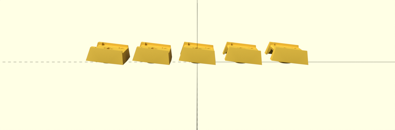 just the
S plates everywhere (14 pieces 1.25U and 58 pieces 1U) — a flatter feel that is simpler to print, since it is a single plate design.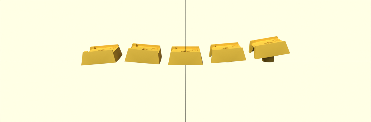 Here you will need
R1 to R5: 4x 1.25U R1, 10x 1U R1, 4x 1.25U R2, 12x 1U R2, 2x 1.25U R3, 12x 1U R3, 2x 1.25U R4, 12x 1U R4, 2x 1.25U R5, 12x 1U R5.To change a profile or add your own, edit the shared
parts/keycap_stem/keycap_stem.scad or add a
file to parts/keycap_stem/variants/, then run
parts/keycap_stem/build_stems.sh — see parts/README.md.
Status display holder (or cover/dummy in case no status display is used), can be 3D printed. parts/export/display_holder/display_holder_r1.stl / parts/export/display_holder/display_holder_dummy_r1.stl
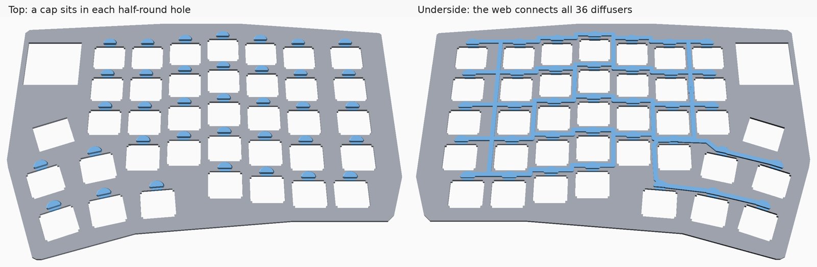
LED diffuser frame (optional, recommended) - one part per half. Each key's LED shines through a half-round hole in the plate, and without a diffuser it shows as a bright point. The frame holds all 36 diffusers of one half at their plate positions, connected by a web under the plate. Print it in resin (SLA): it is thin, and the web is close to the 0.8mm minimum wall a print service accepts.
parts/export/diffuser/diffuser_frame_left.stl / parts/export/diffuser/diffuser_frame_right.stl (the _4x files stack four copies on top of each other, joined by a sprue so that a print service counts one part; the slicer still needs supports between the copies, and you cut the pins off before fitting)
With the frame you need the other spacer, spacer_diffuser_frame.stl (see Spacer above), because the plain spacer has no room for the web.
Transparent keycap covers - 72 pieces (from relegendable keycaps like these), 58x 1U and 14x 1.25U. Various sources sell them on Alibaba, AliExpress, Amazon & Co.
Optional rotary encoder (EVQWGD001 or Alps EC11 Encoder), pimoroni trackball or 23mm cirque trackpad (and a 12 pin FPC cable with pins on the same side, about 50mm to 70mm). For the trackpad you will need another 3D printed holder, either a high one or a low one: 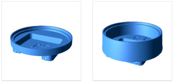 parts/export/cirque_insert/cirque23_slim_insert_r8.stl
parts/export/cirque_insert/cirque23_insert_high_r1.stl
If you are not happy with the existing STLs, you can also modify the source file parts/cirque_insert/cirque23_insert.scad or parts/cirque_insert/cirque23_slim_insert.scad. There is also an experimental version for the 35mm cirque track pad: parts/cirque_insert/cirque35_insert.scad.
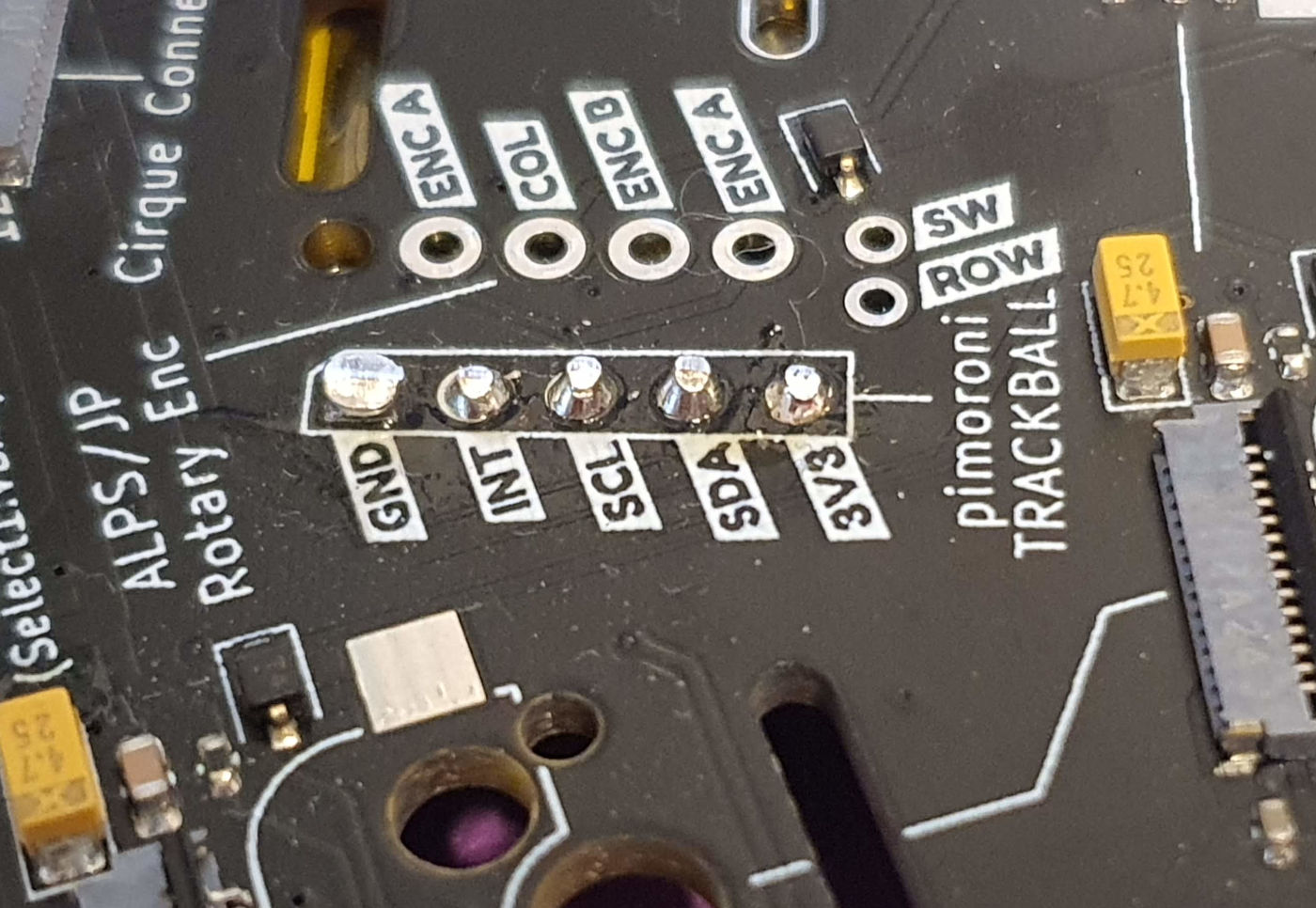
Optional ambient-light + proximity sensor (highly recommended) - a Pimoroni LTR-559 Light & Proximity Sensor breakout plus a matching 5-pin 2.54mm pin header. The Split72 PCB has a dedicated header footprint for it (labelled 3-6V / SDA / SCL / INT / GND), sharing the Cirque I2C bus - no extra wiring. With the sensor fitted, the firmware automatically drives keycap brightness from the measured light level and wakes the displays when your hand approaches. It is entirely optional (the firmware is a clean no-op when no sensor is present) and side-agnostic (works on whichever half you solder it to). You must fit it as the very first assembly step - see the note in Put Everything Together below, because it does not fit through the plate hole and cannot be added later without an almost complete disassembly. 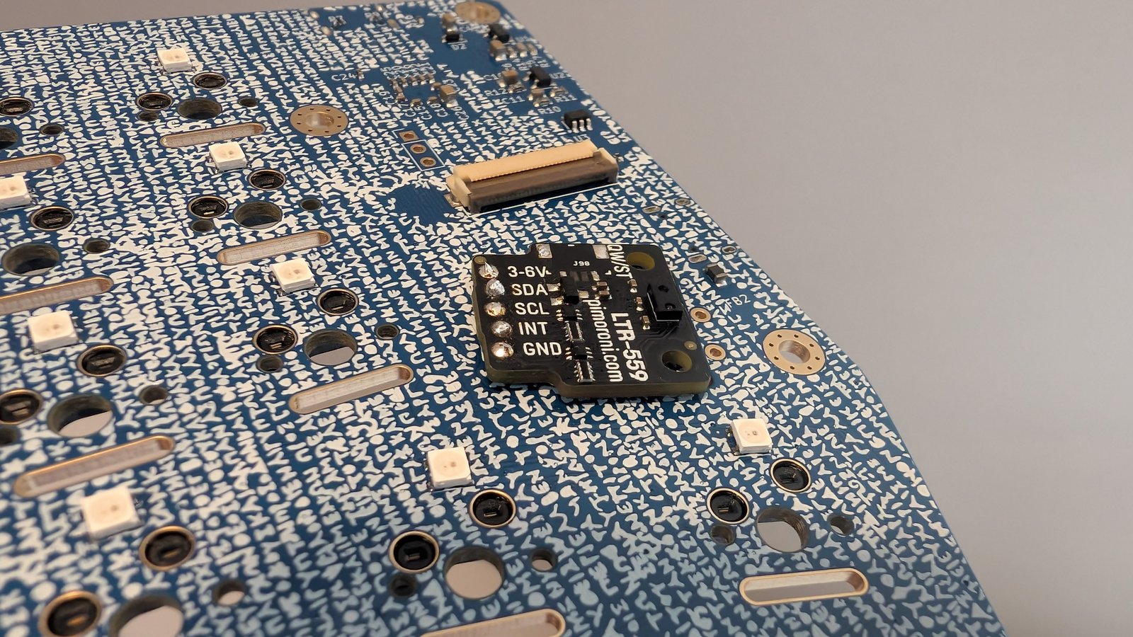 Note: each half has a single expansion slot that takes exactly one of these optional add-ons - a rotary encoder, a pointing device (trackball/trackpad), or the light sensor. So on a given half the sensor is mutually exclusive with the encoder and the pointing device: fitting the sensor means that half has no encoder/trackpad. (You can still put the sensor on one half and a pointing device or encoder on the other.)
Short USB-C to USB-C cable to connect the two sides (maybe around 50cm).
USB-C to USB-A/USB-C to connect to your computer. Note: I had a USB-C to USB-A cable and was sitting in front of a laptop with only USB-C ports. Without a USB-C to USB-C cable at hand, I used an USB-A to USB-C adapter. It turned out this USB-C to USB-A cable + USB-A to USB-C adapter construction was only working then the adapter was connected to the laptop. - better use a USB-C to USB-C right away.
8 M3x10 hex screws with rounded heads and for the current case version (r4 and later, e.g. r7), you also need 8 M3 hex nuts.
Here is my recommended order:
(Optional but highly recommended) Solder the LTR-559 light + proximity sensor - do this FIRST! ⚠️ The sensor board does not fit through the hole in the aluminum plate, so it has to be soldered on before the plate goes on. If you add it later you will have to almost completely disassemble the keyboard again. So if there is any chance you want it, fit it now - it is optional in firmware and costs you nothing if you later decide not to use it. ⚠️ Each half has a single expansion slot shared by the sensor, the rotary encoder and a pointing device (trackball/trackpad) - only one of the three fits per half. So fitting the sensor means no encoder or trackpad on that half (you can still fit one of those on the other half). Decide before you start soldering.
The Split72 PCB has a labelled 5-pin footprint for the sensor (3-6V / SDA / SCL / INT / GND). Solder the sensor exactly like this:
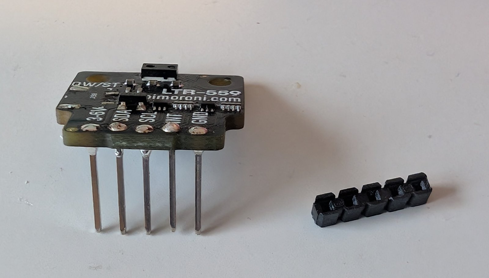
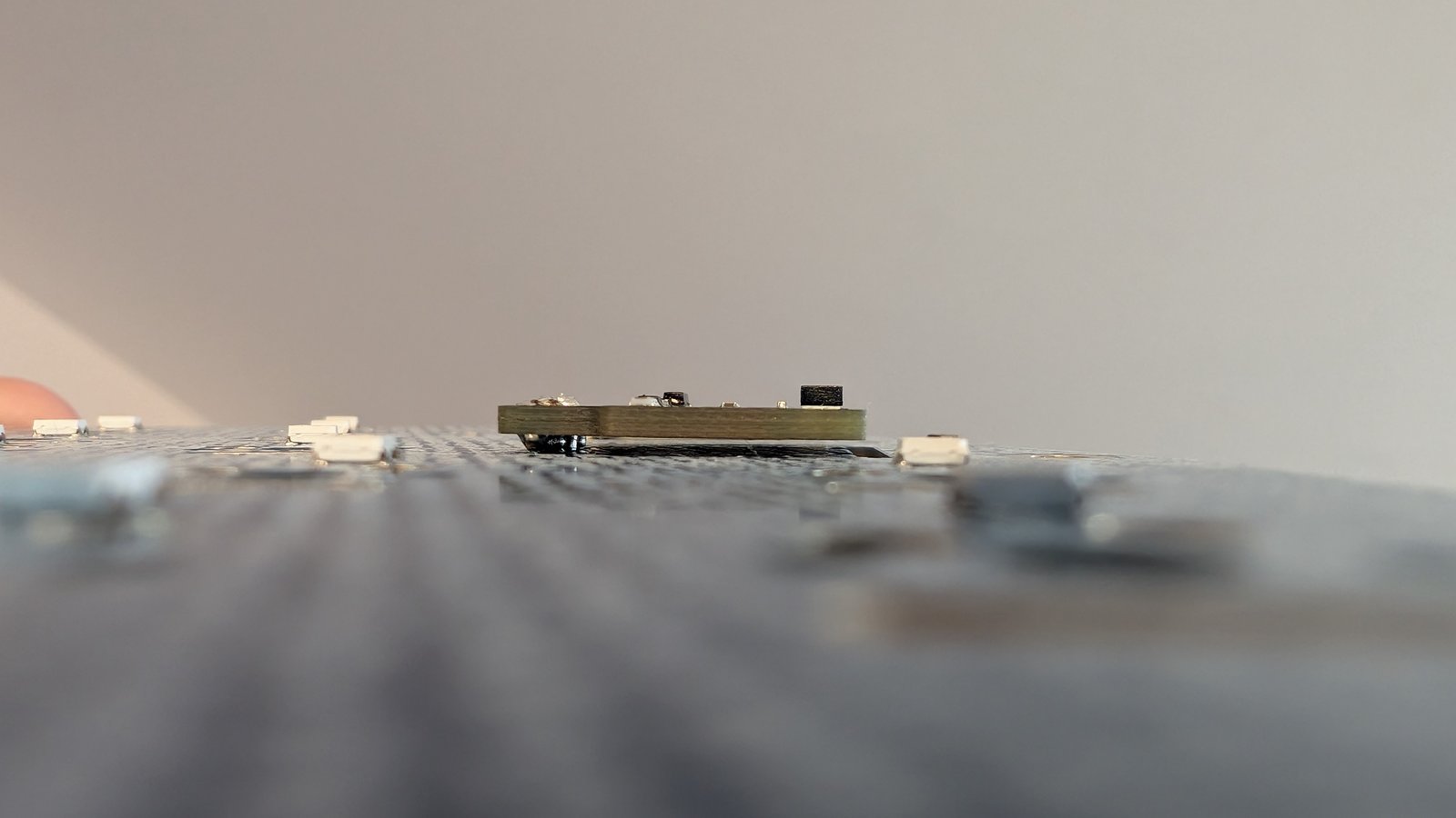
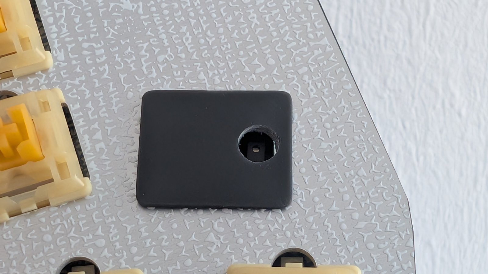
The sensor is auto-detected on whichever half you solder it to - no firmware option to enable. See the firmware readme for how it drives auto-brightness and proximity wake.
(Optional) Fit the LED diffuser frame into the plate - do this first, before anything else touches the plate. Hold the frame under the plate so that each diffuser goes up through its own switch opening. Then slide the frame about 5.5mm, so that each diffuser moves out of the switch opening and into the half-round LED hole next to it, until every diffuser sits in its half-round. The caps on the top and bottom hold the plate between them, and the switches stop the frame from sliding back later, so no glue is needed. Do this while the plate is free: the slide needs the space under the plate, which the spacer fills once the plate is on it.
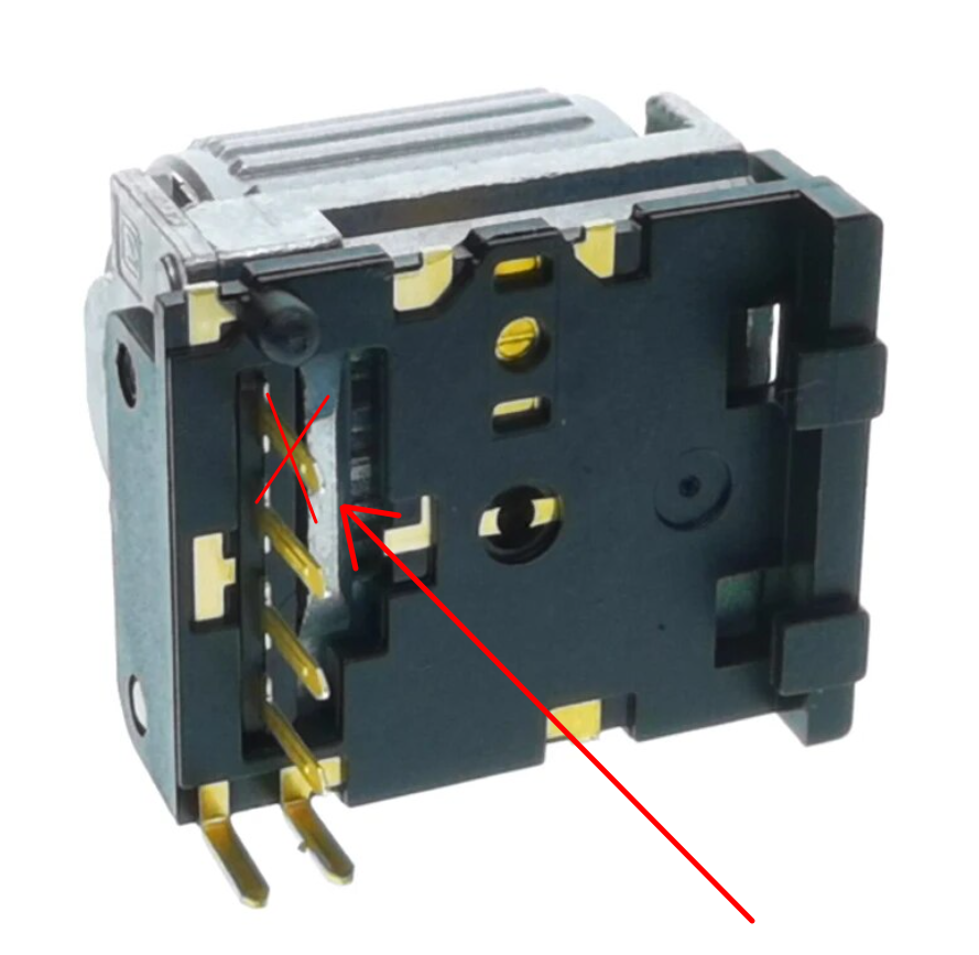
In case you want to use an Alps EC11 Encoder or some remaining stock of the not any more produced EVQWGD001, put it on the PCB and also put the keyboard plate once on top to make sure your encoder fits! In case of the EVQWGD001, you have to remove the last pin, before soldering it to the PCB Juts clip it away. DO NOT solder it to the PCB, or otherwise it will not work:
 Depending on the type of EC11 encoder, you maybe want to put a piece of Kapton tape over the legs, in case they come close to the plate (it was not necessary for mine, but there are different kinds out there).
For the pimoroni trackball, please solder on the header without the little plastic distance holder. There are various ways to do that: Either solder them on and push the plastic with some pliers off the pins (and clip away the pins on the front side of the trackball so that it is flush) or insert them from the front side, solder them on and then clip away the plastic parts. The pins are still long enough. Just go for something that works for you.
Next, put some Kapton tape on the back side of the trackball and solder it to the keyboard PCB. Make sure it is even on the front side, there will be an average 1 to 2mm distance:
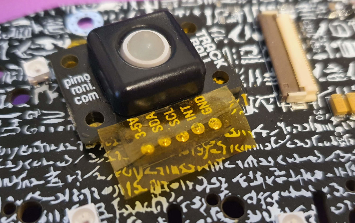 Finally also cover the trackballs front side with Kapton tape like in the picture above (or anything that pleases your eye and insulates) to avoid any shorts since the top plate is made out of Aluminum.
In case you use the 23mm cirque trackpad, first remove R1 from the backside of the trackpad's PCB (with a solder iron or maybe a sharp knife) to activate I2C instead of SPI. Then connect the 12 pin FPC to the trackpad (and mind the pin 1 marking on the trackpad + I made my own marking on the FPC to make sure):
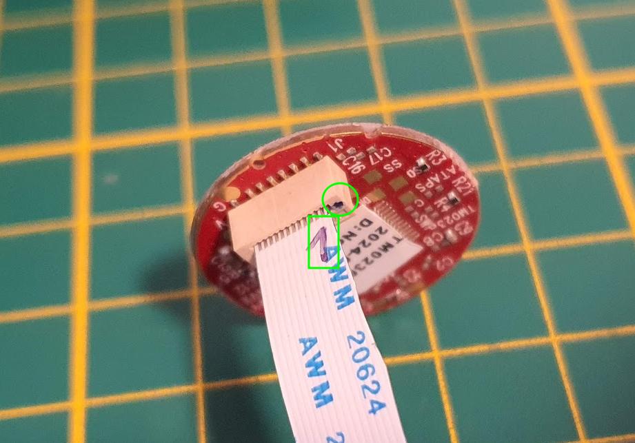 Then, put it into the 3D printed holder. You can fix the trackpad with some adhesive tape or a few drops of super glue into the holder. Wait with connecting it to the PCB:
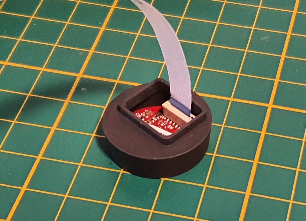 There is also an experimental version for the 35mm trackpad, take a look at the parts folder.
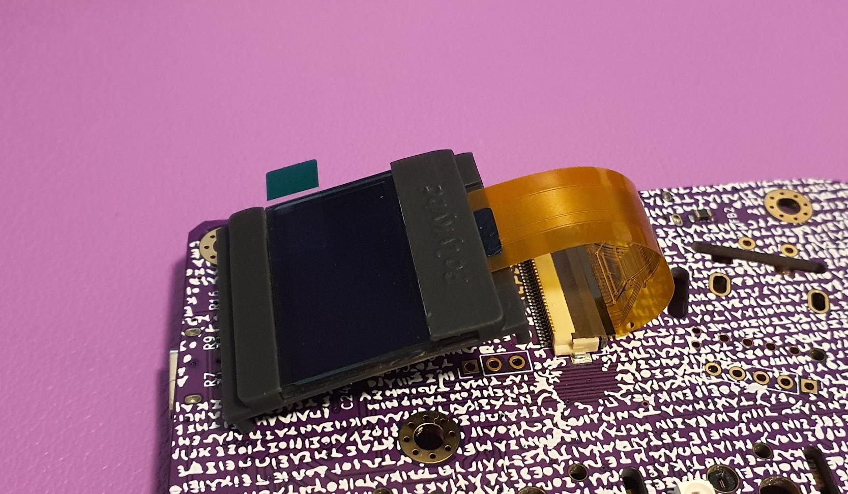
Insert the 0.96 inch status display into the display holder (bend the holder back and let it snap back to bracket the display). Connect the FPC with the socket on the PCB and lock it by lowering the brown flap on the FPC side (if you don't have a status display just close the cut out with the blind lid):
Put the spacer on top. If you fitted the LED diffuser frame, this must be spacer_diffuser_frame.stl.
While putting the plate on top of the assembly, fit the status display holder (or blind) into the plate from the plates back side:
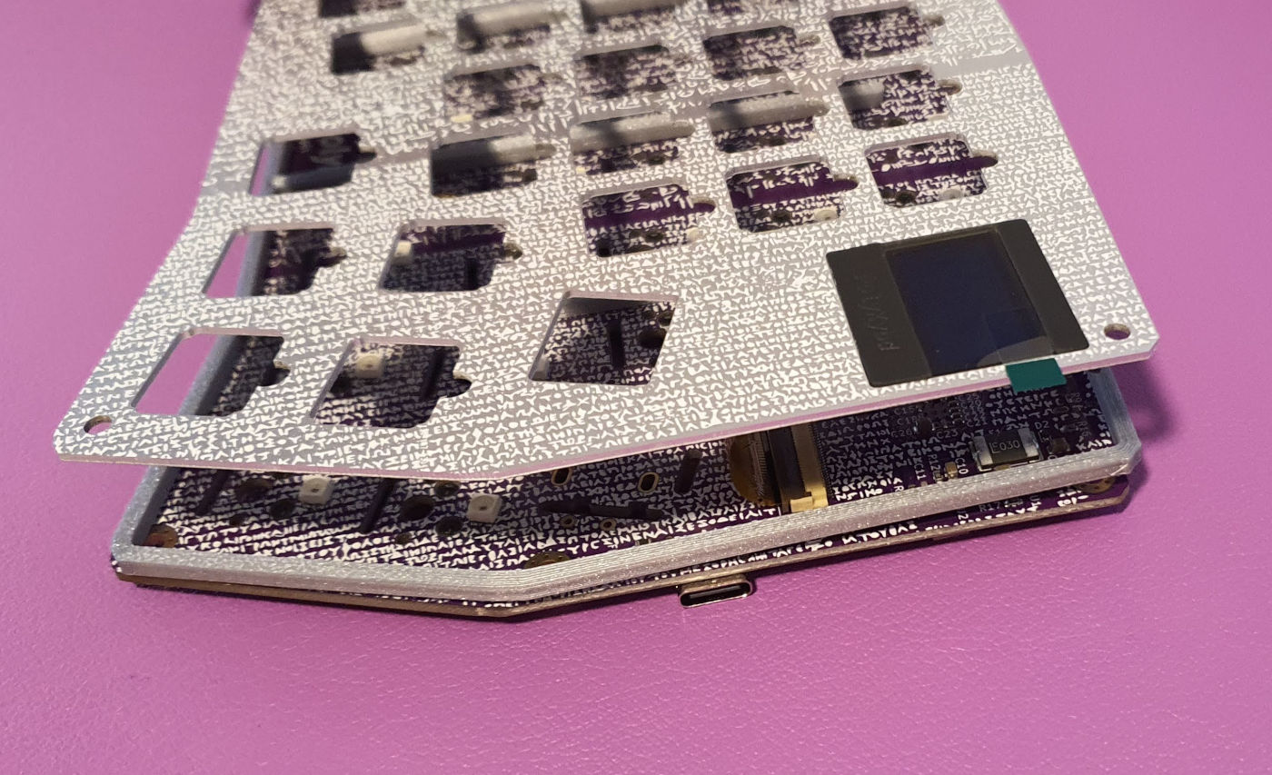 Then, the plate rests on the spacer, which again rests on the PCB. I pushed in two screws temporarily to align plate and PCB:
Now would be the time to fit in the optional cirque trackpad. First get the FPC cable through the slot:
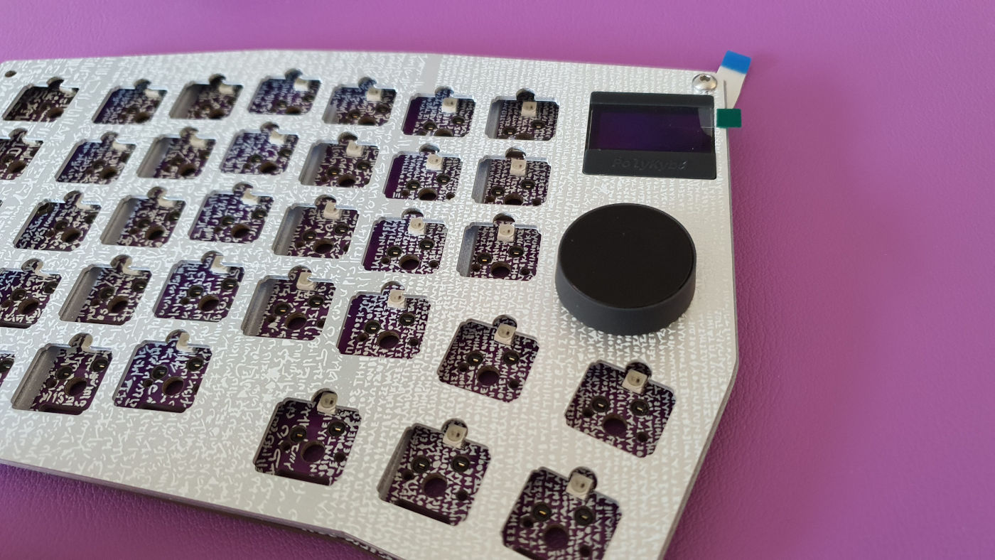
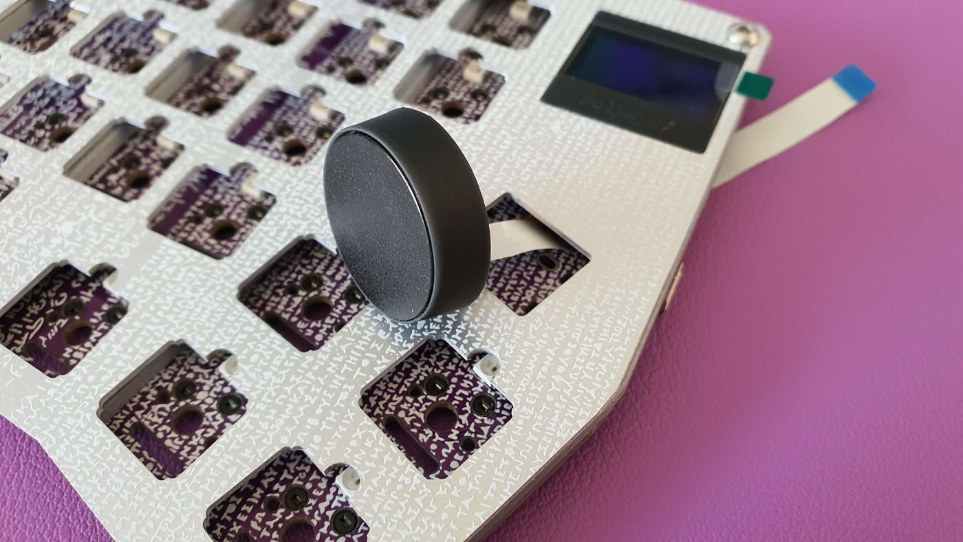 Next, push in the trackpad holder. It is a press-fit, so no glue needed, just push:
 Finally insert the FPC cable into the cirque socket and lock it by lowering the little flap on the back side of the socket (again make sure that pin 1 meets the side with the little 1 next to the socket):
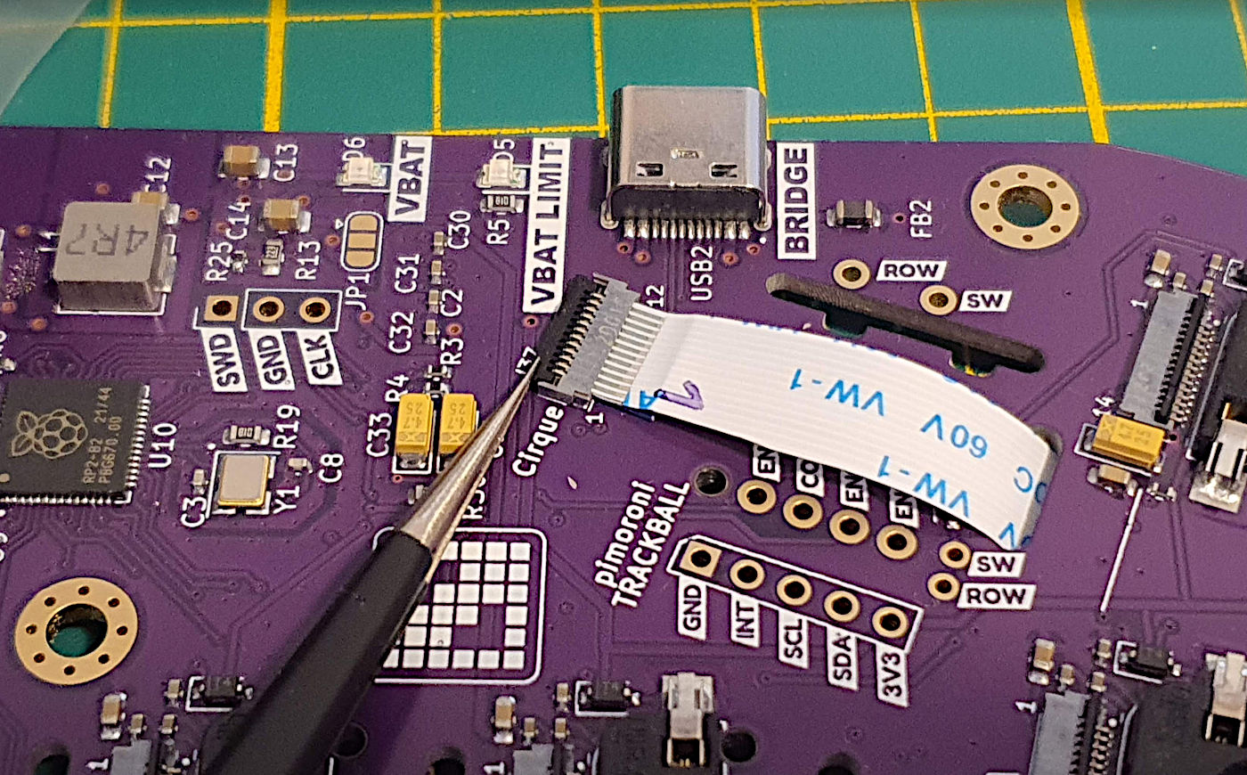 Depending on the keyboard side (left/right), the slot for the FPC to go through is located very close to the trackpad socket or a bit further away as on the picture.
Assemble all 72 keys: Put the stem on the key switch, put the flex cable through the LED slit of the key switch and and align the display. Finally put the clear keycap over it and make sure it sits flat on the stem. The display will slide into the stem when covering with the clear keycap. You don't need to pre-bend the flex cable. I rather recommend against bending it as you might damage it. The following images shows these 3 steps: 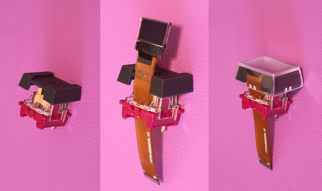 Now repeat this for every key-switch. A fully prepared keyboard side of switches might look like this:
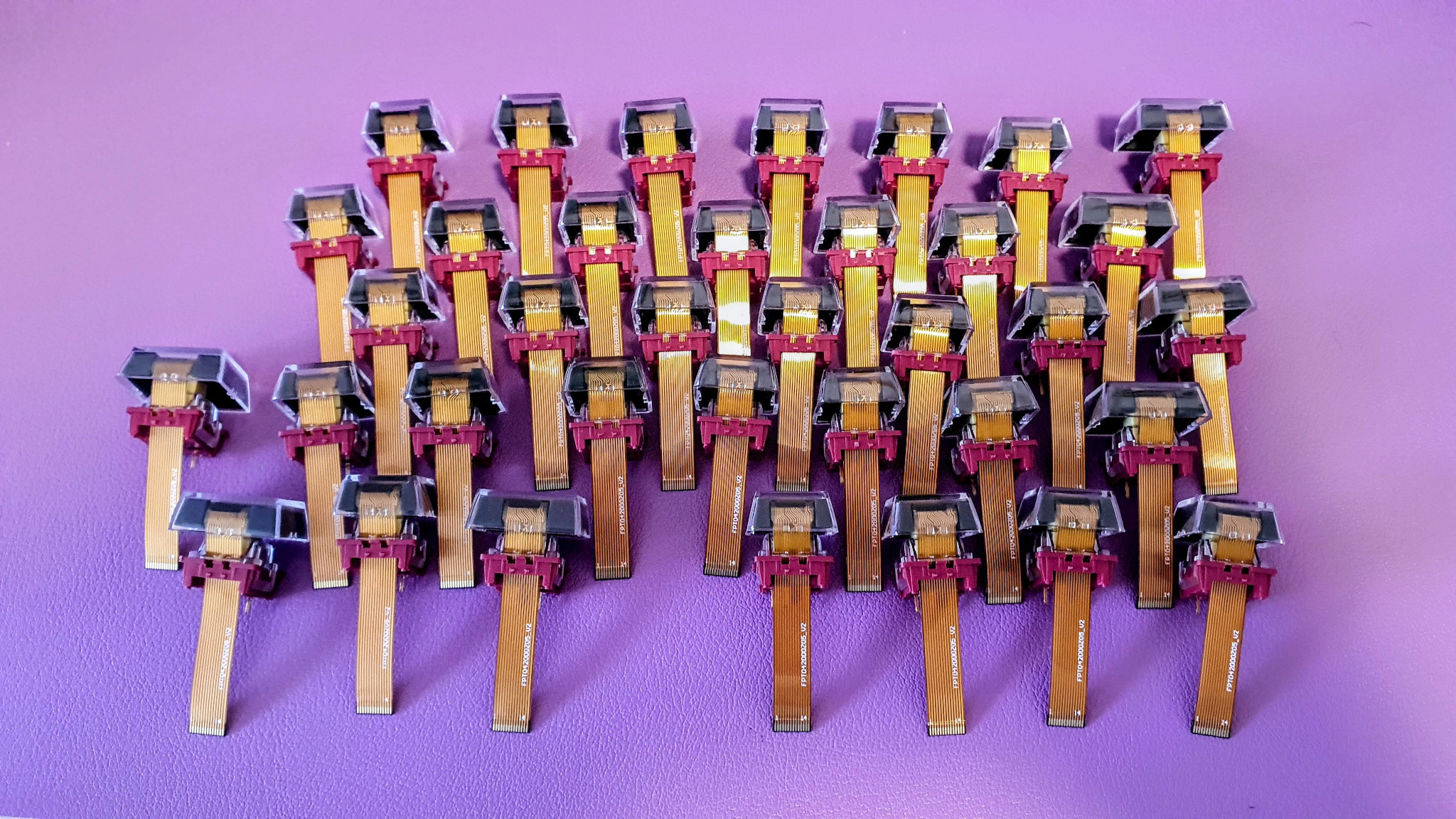
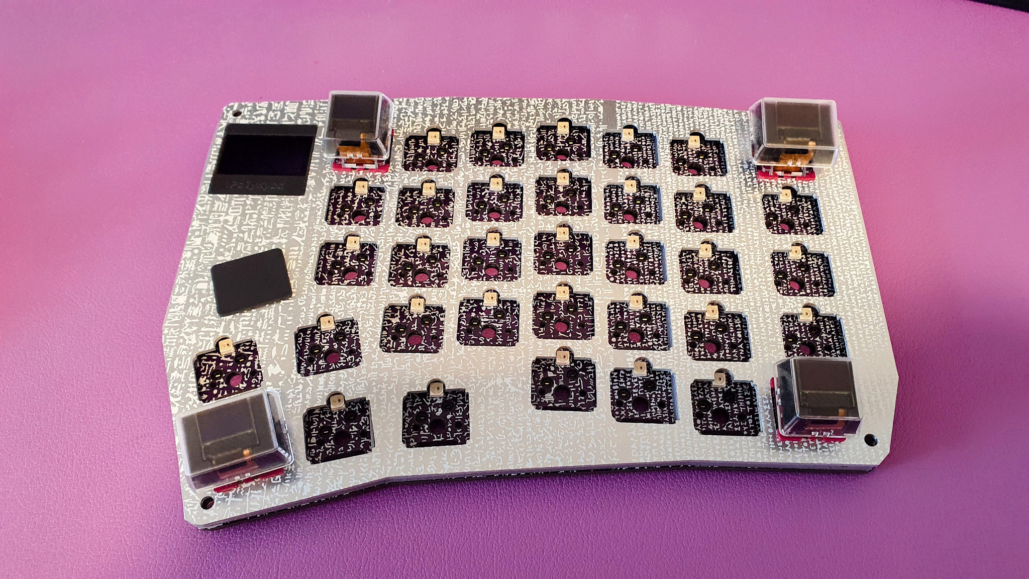
Push in one assembled key switch at each corner so that everything aligns properly.
To do that, first insert the flex cable into the PCB slot and push the key switch STRAIGHT into the hot swap socket.
DO NOT keep pushing if you feel resistance half way to the bottom, there is a danger that you detach the hot-swap from the PCB. In that case, get the switch out again, make sure the pins aren't bent and try again!
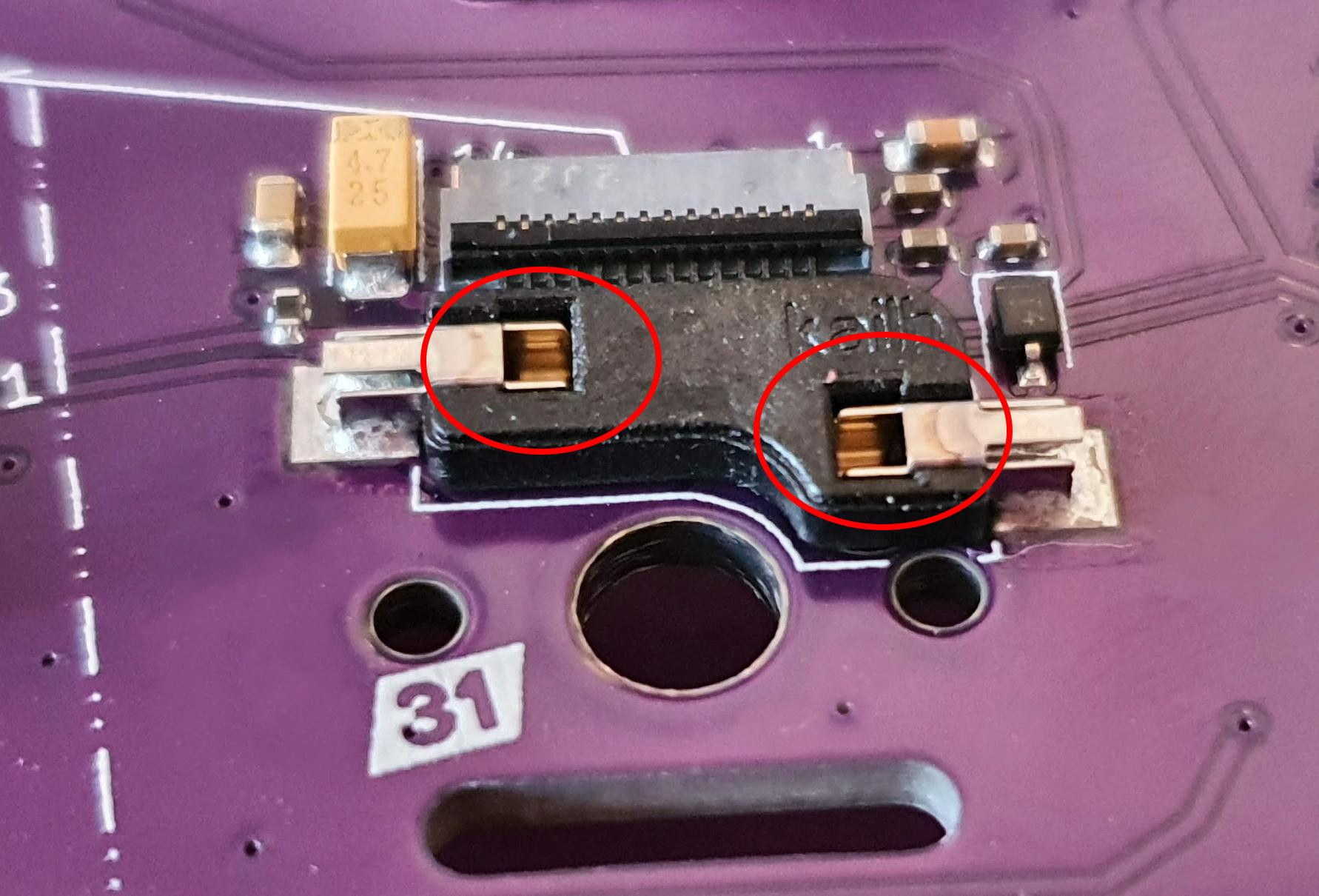
On the backside, you can check if both pins have been inserted properly:
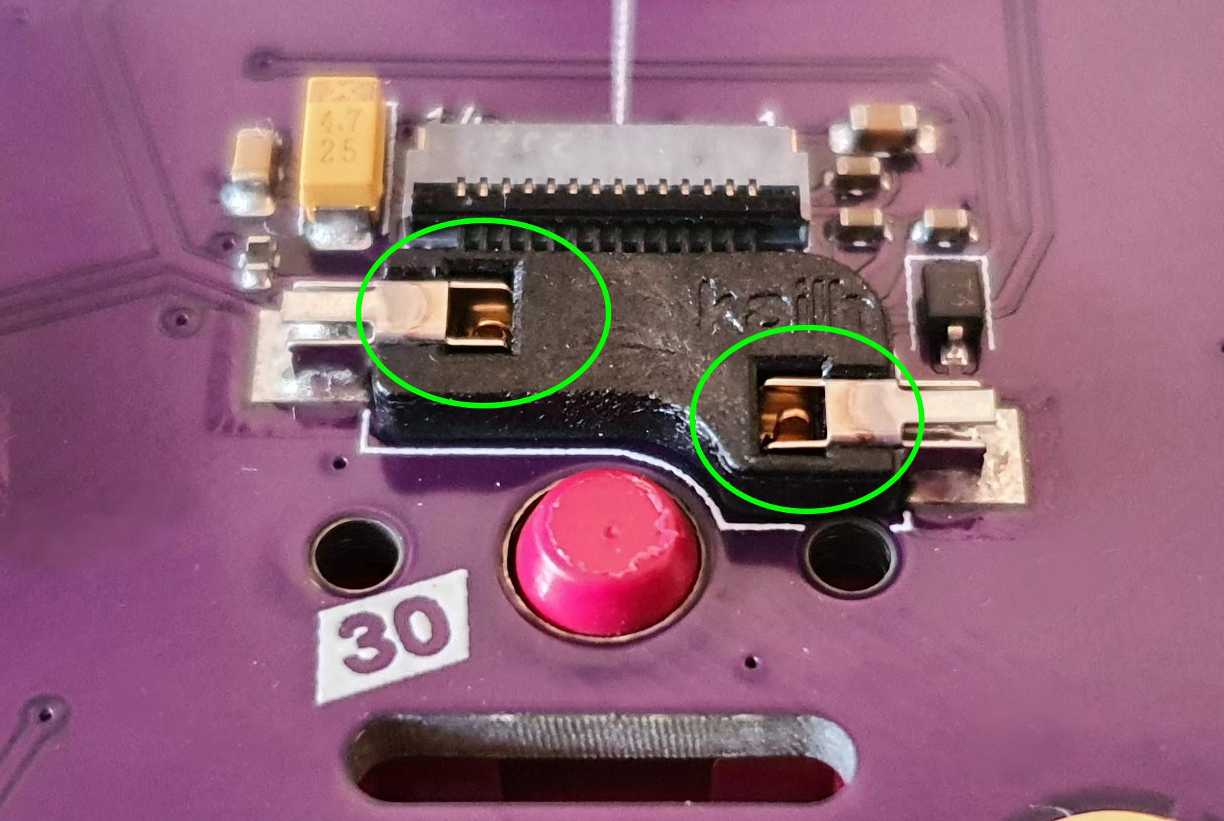 Here, only one pin is in the hot-swap socket. Pull the key switch out again, straighten the bent pin and reinsert carefully:
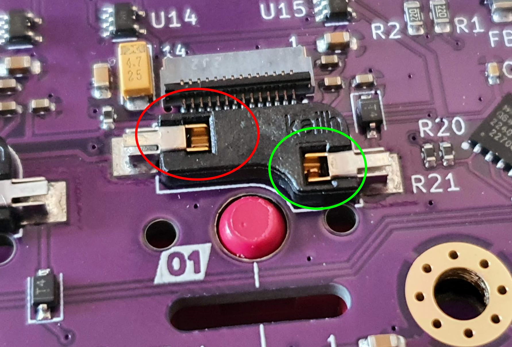 This is how it looks like if there is no key switch inserted:
 Now your assembly should look like this:
Insert the remaining key switches in the same way and check that the pins are visible as indicated above: 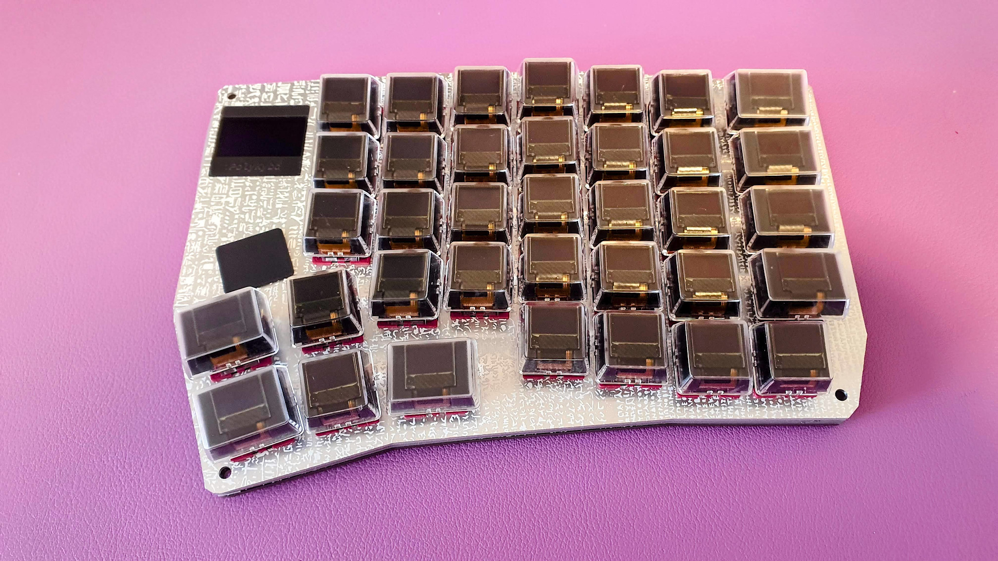
Start inserting the flex cables into the sockets: 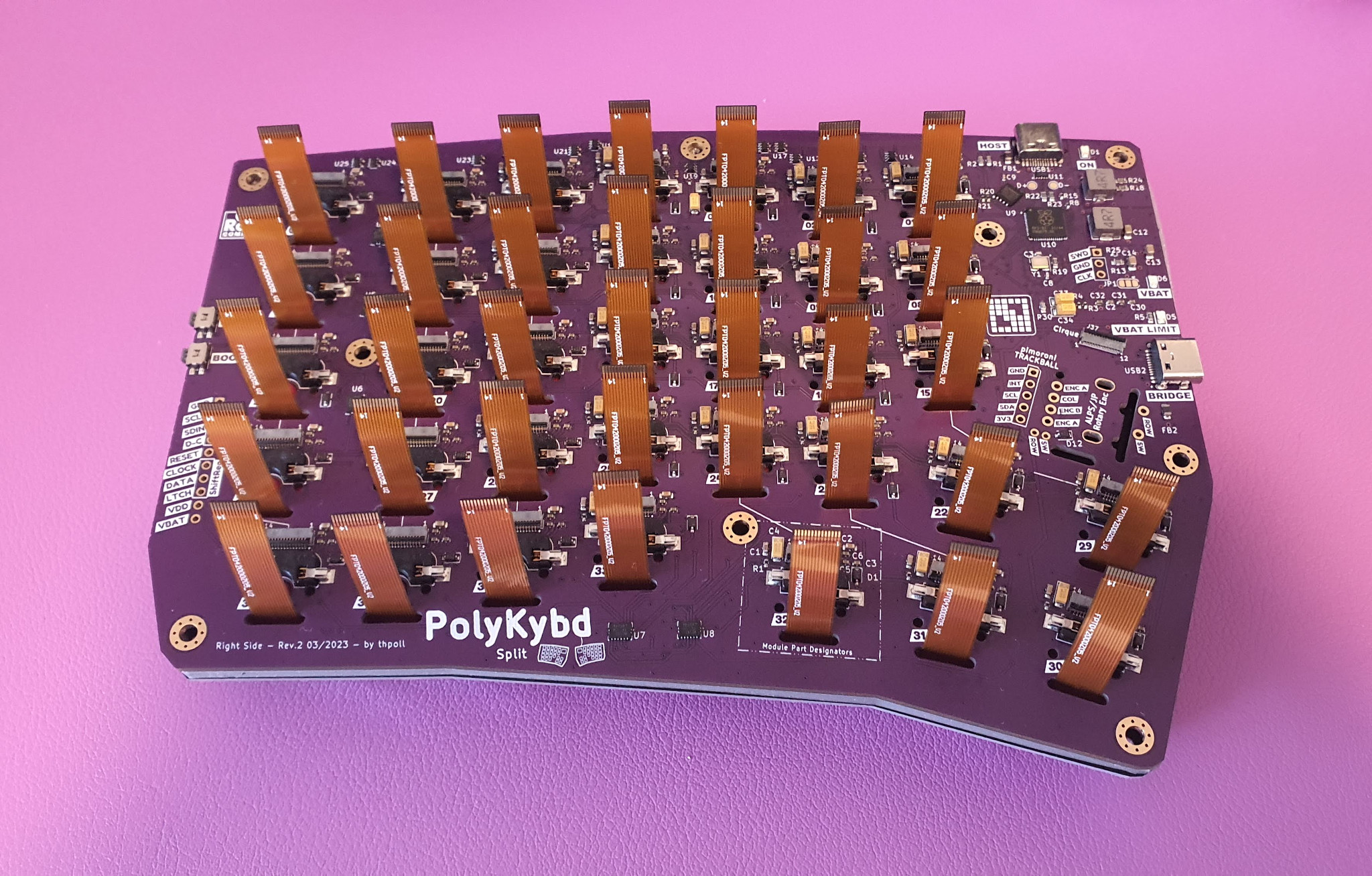 If the flex cable is not long enough for you, press the key switch to make it longer. But it should also work without doing that. You cas use some tweezers or also a toothpick to first lift the flap to unlock the socket. Insert the end part into the socket, again recommended with tweezers, but also works without (so with your hands - finger!). After inserting the flex cable, lock the socket. Lower the little flap on the back-side of the socket you lifted at the beginning:
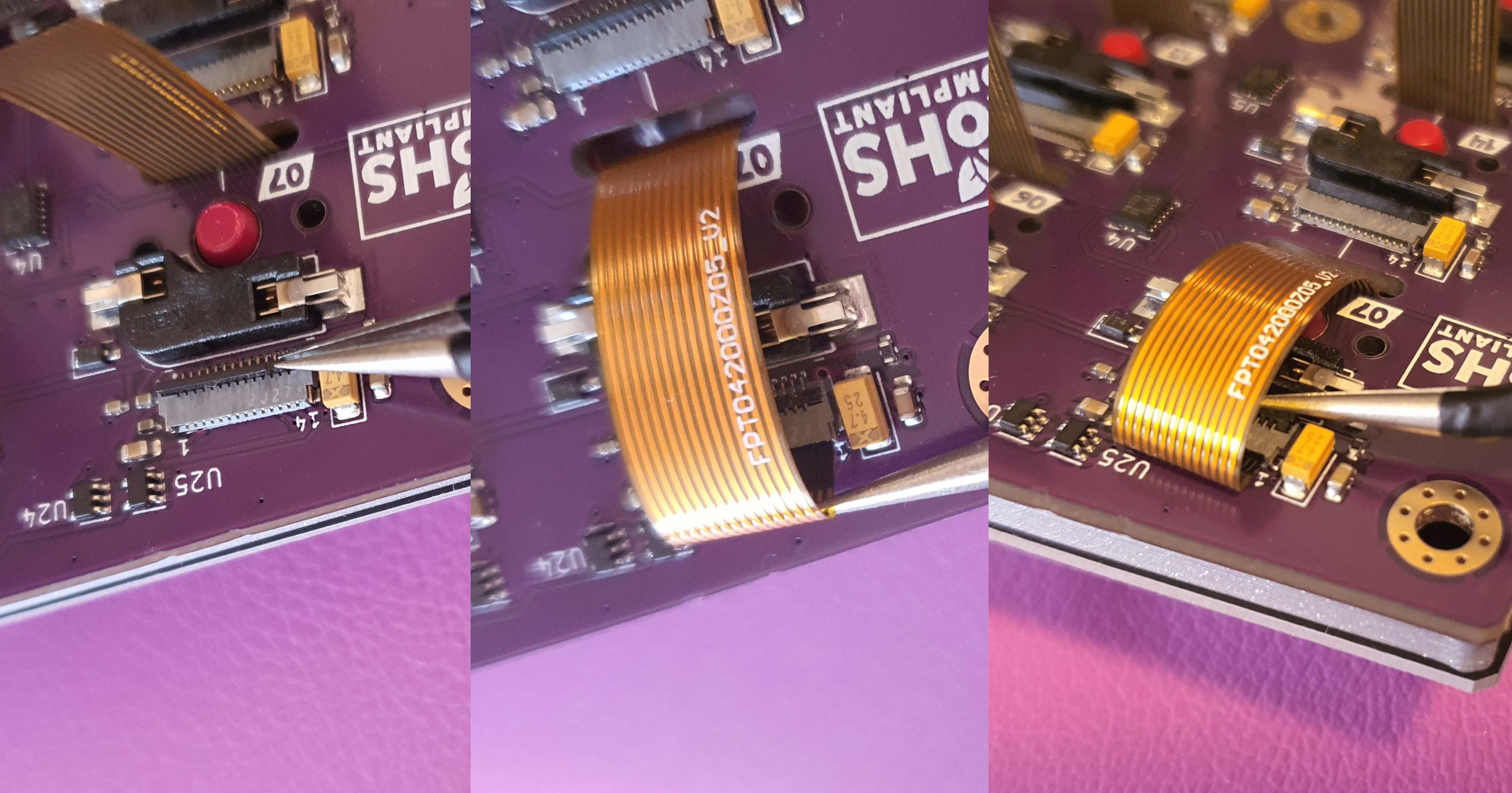 The finished version should look like that:
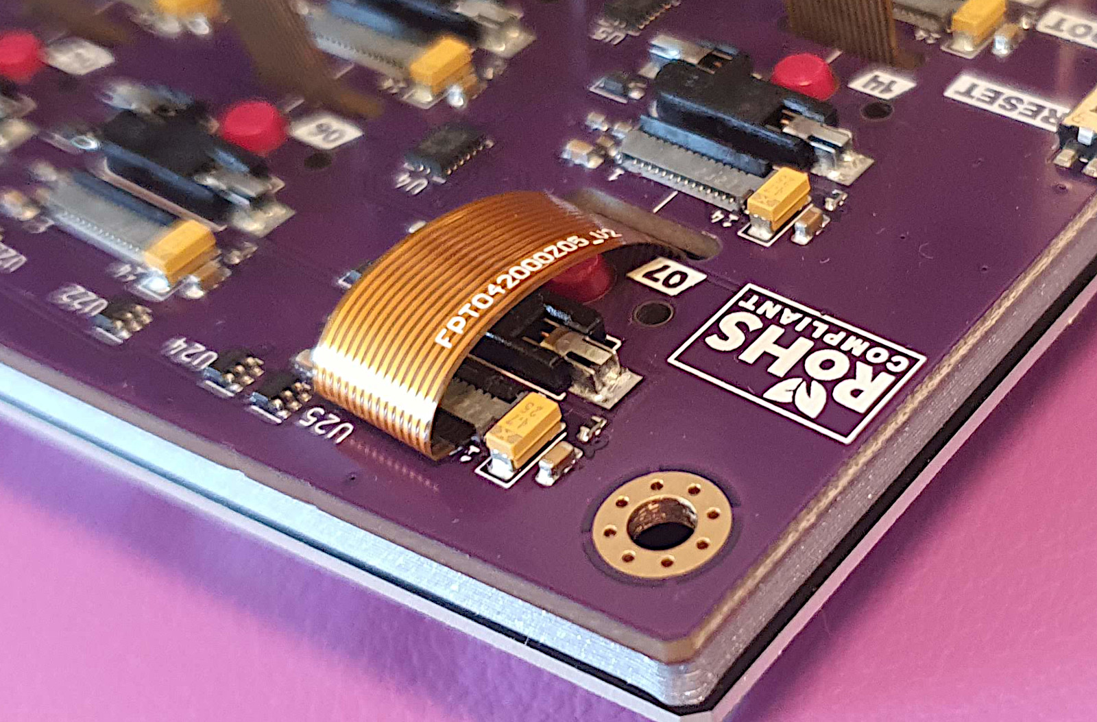 Now repeat this procedure for every flex cable.
In case you have a case with revision r4 or higher it's now time to insert the hex nuts into the corners.
Before putting the whole assembly into the case, do a function check! If you have not yet flashed the firmware to the board, build one according to the instructions on https://github.com/thpoll83/qmk_firmware/blob/PolyKybd/keyboards/polykybd/readme.md and flash by first pressing the boot button and then connecting the USB-C while holding the button. After you connect, just release the button and copy the .hex file to the USB drive and you are set. There is no need to connect the second side (depending on the firmware version). When connected to power, after a second or two, all displays should show some characters. If not, disconnect the cable again, release the lock of the FPC display socket in question and re-insert the FPC cable, lock again and reconnect the USB-C port.
While still connected to USB-C press every key once. Each pressed key should invert its display contents. If not one or both pins might have been bent when inserting the key switch. If that is the case, pull the key switch out again, make the pins straight again and carefully insert one more time.
After we confirmed that all displays and all keys do work, put the assembly into the case: 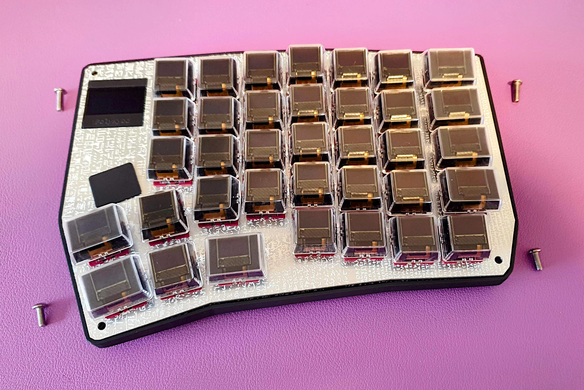 Start on the inner side, where the two halves are connected by the bridge USB-C socket. You maybe have to give it a gentle push on the other side to go in.
Insert the 4 hex screws and tighten them carefully. 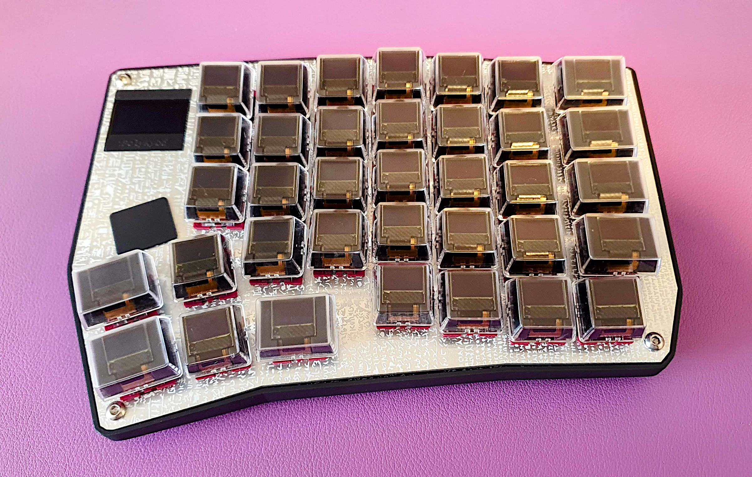 Now repeat with the other side ;)
Connect the two halves with the short USB-C to USB-C cable.
Finally connect the left side with the USB-C cable connecting to the host system and you are done!
Congratulations! You made it! 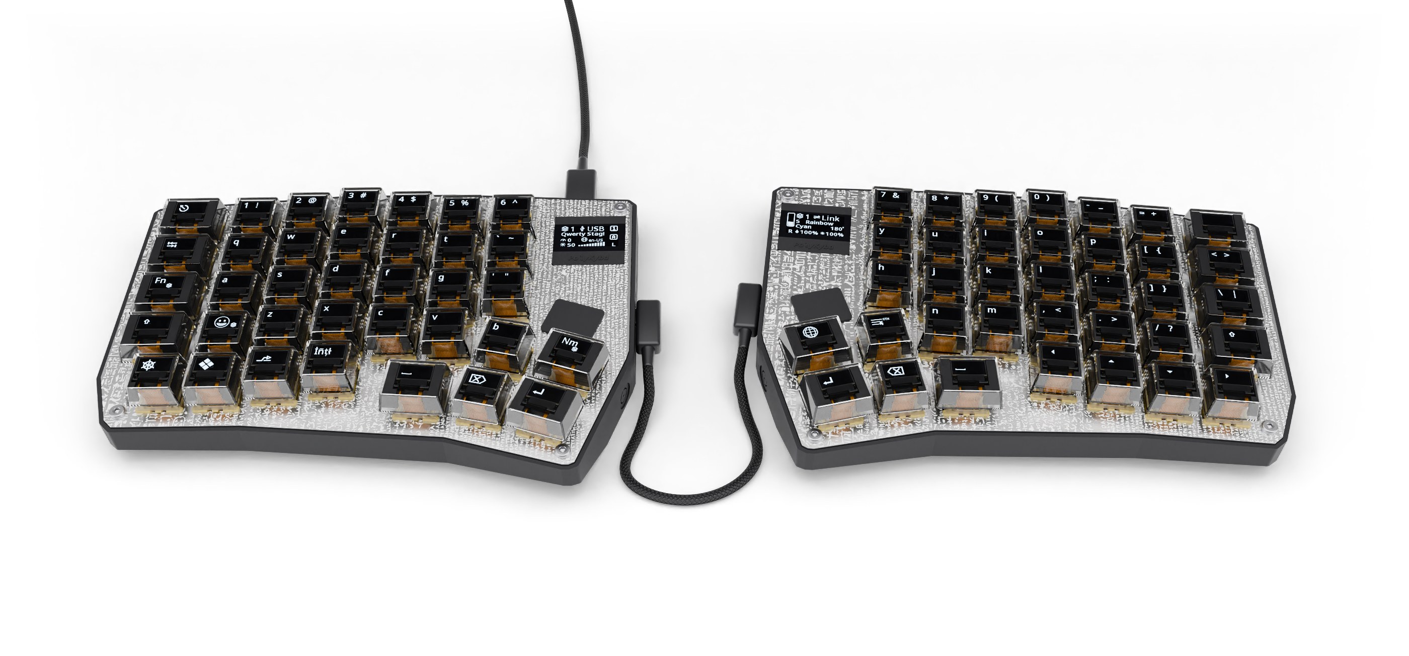 In case you experience any issues, please let me know or make a PR on the build guide!
The fun just starts now! You will recognize that there are a lot of ways to play around with this keyboard.
U+FFFF (basically excluding any emoji, additionally you might have to run reg add "HKCU\Control Panel\Input Method" -v EnableHexNumpad -t REG_SZ -d 1 to enable that feature on Windows)This project has been an incredible amount of work, please consider supporting me if you like it:
https://ko-fi.com/polykb

| Qty | Value | Footprint | References |
|---|---|---|---|
| 18 | 1uF | Capacitor_SMD:C_0805_2012Metric | C18, C19, C24, C25, C30, C31, C36, C37, C42, C43, C48, C49, C54, C55, C60, C61 +2 |
| 18 | 2.2uF | Capacitor_SMD:C_0805_2012Metric | C20, C21, C26, C27, C32, C33, C38, C39, C44, C45, C50, C51, C56, C57, C62, C63 +2 |
| 10 | WS2812B-Mini | poly_kb:WS2812B-Mini | LED_0, LED_1, LED_2, LED_3, LED_4, LED_5, LED_6, LED_7, LED_8, LED_9 |
| 9 | 100nF | Capacitor_SMD:C_0805_2012Metric | C23, C29, C35, C41, C47, C53, C59, C65, C71 |
| 9 | 4.7uF | Capacitor_SMD:C_0805_2012Metric | C22, C28, C34, C40, C46, C52, C58, C64, C70 |
| 9 | Conn_01x01_Female | Connector_PinHeader_1.00mm:PinHeader_1x01_P1.00mm_Vertical | J17, J20, J23, J26, J29, J32, J35, J38, J41 |
| 9 | Conn_01x01_Male | Connector_PinHeader_1.00mm:PinHeader_1x01_P1.00mm_Vertical | J18, J21, J24, J27, J30, J33, J36, J39, J42 |
| 9 | Conn_01x16 | poly_kb:FPC_16_AFC11-S16ICA-00 | J16, J19, J22, J25, J28, J31, J34, J37, J40 |
| 6 | 2k2 | Resistor_SMD:R_0805_2012Metric | R9, R10, R11, R12, R13, R14 |
| 5 | 100n | Capacitor_SMD:C_0402_1005Metric | C2, C3, C4, C5, C6 |
| 4 | 1u | Capacitor_SMD:C_0402_1005Metric | C7, C13, C14, C16 |
| 4 | 22 | Resistor_SMD:R_0805_2012Metric | R16, R17, R18, R19 |
| 4 | MountingHole_Pad | MountingHole:MountingHole_4.3mm_M4_Pad_Via | H1, H2, H3, H4 |
| 3 | 1k5 | Resistor_SMD:R_0805_2012Metric | R3, R20, R21 |
| 2 | 100k | Resistor_SMD:R_0603_1608Metric | R1, R2 |
| 2 | 20p | Capacitor_SMD:C_0603_1608Metric | C11, C12 |
| 2 | 30p | Capacitor_SMD:C_0402_1005Metric | C9, C10 |
| 2 | 74HCT595 | Package_SO:SOIC-16_3.9x9.9mm_P1.27mm | U3, U4 |
| 2 | SolderJumper_2_Open | Jumper:SolderJumper-2_P1.3mm_Open_TrianglePad1.0x1.5mm | JP1, JP2 |
| 1 | /MR | Connector_PinHeader_2.54mm:PinHeader_1x03_P2.54mm_Vertical | J5 |
| 1 | /OE | Connector_PinHeader_2.54mm:PinHeader_1x03_P2.54mm_Vertical | J4 |
| 1 | 100R | Inductor_SMD:L_0805_2012Metric | FB1 |
| 1 | 10k | Resistor_SMD:R_0402_1005Metric | R6 |
| 1 | 10n | Capacitor_SMD:C_0402_1005Metric | C8 |
| 1 | 32.768KHZ | poly_kb:SMD-0832_4P | Y2 |
| 1 | 39n | Inductor_SMD:L_0402_1005Metric | L1 |
| 1 | 4u7 | Capacitor_SMD:C_0603_1608Metric | C1 |
| 1 | 5k1 | Resistor_SMD:R_0603_1608Metric | R15 |
| 1 | 8MHZ | Crystal:Crystal_SMD_5032-2Pin_5.0x3.2mm | Y1 |
| 1 | ADC1 | Connector_PinHeader_2.54mm:PinHeader_1x02_P2.54mm_Vertical | J14 |
| 1 | BOOT0 | poly_kb:Switch_THT | SW1 |
| 1 | BOOT1 | poly_kb:Switch_THT | SW2 |
| 1 | D_Small | Diode_SMD:D_SOD-123F | D1 |
| 1 | I2C1 | Connector_PinHeader_2.54mm:PinHeader_1x04_P2.54mm_Vertical | J6 |
| 1 | I2C2 | Connector_PinHeader_2.54mm:PinHeader_1x04_P2.54mm_Vertical | J7 |
| 1 | I2C3 | Connector_PinHeader_2.54mm:PinHeader_1x04_P2.54mm_Vertical | J11 |
| 1 | Key_Cols_1 | Connector_PinHeader_2.54mm:PinHeader_1x16_P2.54mm_Vertical | J3 |
| 1 | Key_Cols_2 | Connector_PinHeader_2.54mm:PinHeader_1x05_P2.54mm_Vertical | J2 |
| 1 | Key_Rows | Connector_PinHeader_2.54mm:PinHeader_1x06_P2.54mm_Vertical | J1 |
| 1 | Power | LED_SMD:LED_0603_1608Metric | D4 |
| 1 | RESET | poly_kb:Switch_THT | SW3 |
| 1 | Reset | LED_SMD:LED_0603_1608Metric | D2 |
| 1 | SHIFTR_K10-K16+C | Connector_PinHeader_2.54mm:PinHeader_1x08_P2.54mm_Vertical | J9 |
| 1 | SPI1 | Connector_PinHeader_2.54mm:PinHeader_2x04_P2.54mm_Vertical | J8 |
| 1 | SPI2 | Connector_PinHeader_2.54mm:PinHeader_2x04_P2.54mm_Vertical | J10 |
| 1 | SPI4 | Connector_PinHeader_2.54mm:PinHeader_2x04_P2.54mm_Vertical | J13 |
| 1 | STM32F303VCTx | Package_QFP:LQFP-100_14x14mm_P0.5mm | U1 |
| 1 | SWD | Connector_PinHeader_2.54mm:PinHeader_2x05_P2.54mm_Vertical | J15 |
| 1 | Status | LED_SMD:LED_0603_1608Metric | D3 |
| 1 | UART3 | Connector_PinHeader_2.54mm:PinHeader_1x04_P2.54mm_Vertical | J12 |
| 1 | USBLC6-2SC6 | Package_TO_SOT_SMD:SOT-23-6 | U5 |
| 1 | USB_C_Plug_USB2.0 | Connector_USB:USB_C_Receptacle_Palconn_UTC16-G | P1 |
| 1 | XC6206P332MR | Package_TO_SOT_SMD:SOT-23 | U2 |
It measures 116.8 × 86.4 mm and has 2 copper layers, 1.6 mm thick.
161 parts, built around the 74HCT595D, USBLC6-2SC6, XC6206P332MR and WS2812B-MINI-X2. The full list of its parts is on this page, with links to each part's symbol and footprint where PCBKit's library has them.
From the thpoll83/PolyKybd repository on GitHub, at the commit this page was made from: the board is backup/poly_kb/poly_kb.kicad_pcb. PCBKit opens the board in the browser, with nothing to install.
Its repository publishes it under the CERN-OHL-W-2.0 licence: you may reuse it on that licence's terms (keep the author's notice, and for a copyleft licence share your changes alike).


yacchin1205/puchi-pix
A tiny pixel art display kit powered by STM32G030F6P, with a 96x64 OLED (SSD1331) or TFT display.

hoeken/frothfet
Yarrboard load controller board with current sense, volt sense, fuses, and sender support.

thebenedict/seattletransit-hardware
Schematic and PCB for a circuit board map of Seattle area public transit.


fubiniricci/NOVA-S3
A 40 × 30 mm, two-layer ESP32-S3 development board, designed and generated programmatically from the official KiCad libraries with a custom grid-based auto-router.

moclei/motion-play
Motion sensing project for fast moving objects moving through a plane. With directionality.
