
2 layers229.9 × 111.8 mm

 thorpej/ft230x-breakout
FT230X breakout board
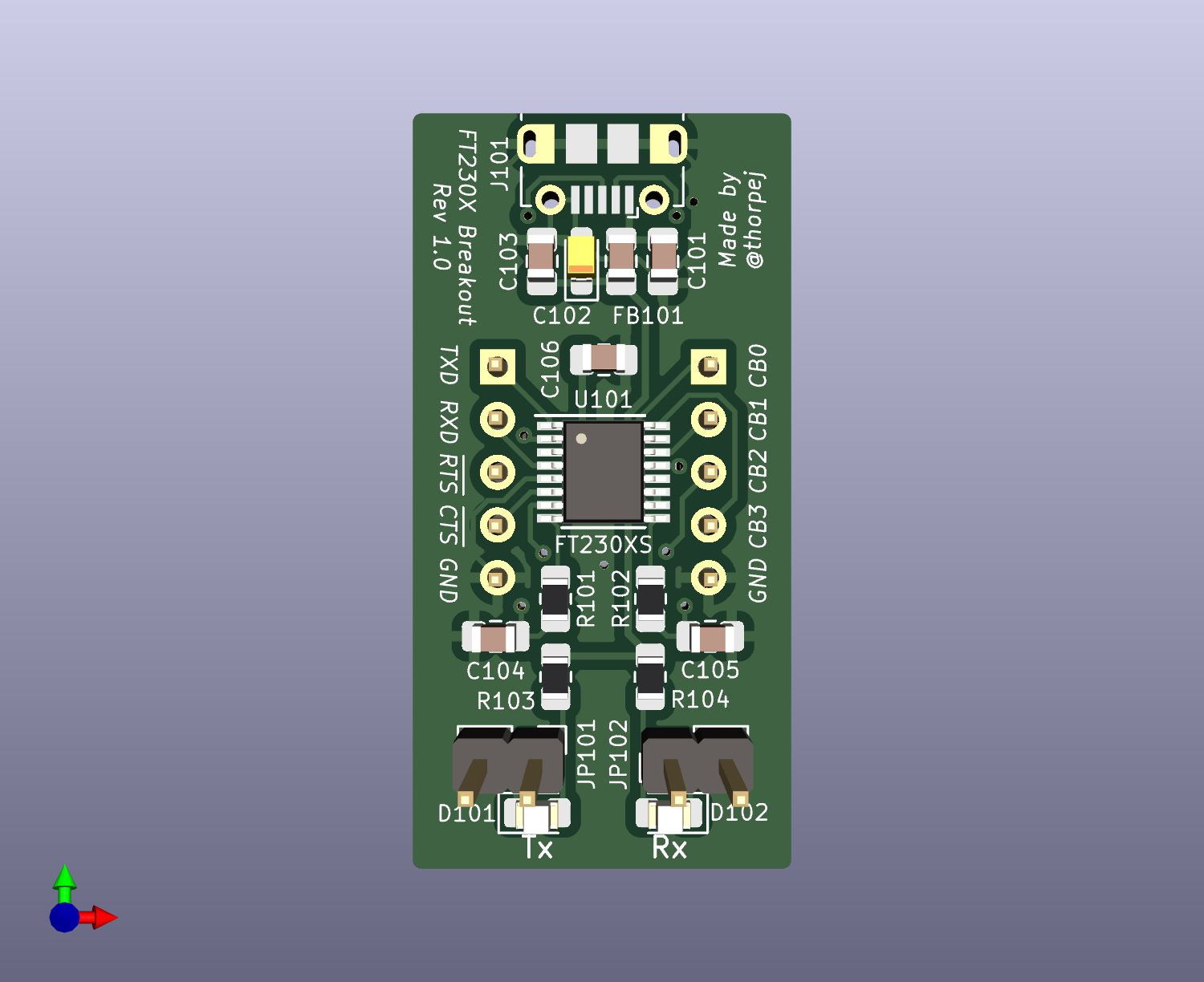
Ft230x breakout is an open-source printed circuit board by thorpej, from the thorpej/ft230x-breakout repository on GitHub. It is a 2-layer board of 18.2 × 36.4 mm with 20 parts on 21 nets, routed with 149 tracks and 10 vias.
It is built around the FT230XS-R. Its parts include 6 capacitors, 4 resistors, 3 connectors, 2 diodes and 1 IC. It belongs with the interfaces and adapters and microcontroller boards boards of this library.
This is a fairly straight-forward breakout board for the FTDI FT230X USB UART. The circuit is more-or-less the example bus-powered circuit in the FT230X data sheet, and all of the I/O pins are simply brought out to pin headers. You can point them down for inserting into a breadboard, or you can point them up for connecting with Dupont wires. The board is pretty small, so there are no mounting holes.
This work is licensed under the Creative Commons Attribution ShareAlike 4.0 International license.

At the time I designed this, the FT230X was the simplest of FTDI's USB UARTs. It has TXD, RXD, RTS, and CTS serial signals, plus four general purpose I/O pins that have several available functions (see the data sheet). The default configuration for two of those pins is to drive transmit and receive LEDs, and so I went ahead and included those LEDs on the board along with jumper headers to enable them. If the jumpers are not installed, then the two pins (CB1 and CB2) are completely isolated from the LEDs, so they are safe to use for whatever purpose you wish.
I designed and built this board mainly as a learning experience; I am planning to use the FT230X in some other projects, and wanted to prove to myself that I could do the necessary PCB layout and assembly work the part requires. I'm absolutely positive that better design is possible, but I'm just a hobbyist with middle-aged-guy eyesight, so this is what you get! :-)
With the exception of the pin headers, everything on this board is surface-mount, so you will need to be comfortable with surface-mount soldering. The FT230XS is probably going to be the trickiest part to solder, followed by the micro USB connector. Both of those should be fairly doable with both paste and hot air or drag soldering (and the USB connector has through-holes for mounting). There are lots of surface-mount soldering tutorials on YouTube if you want to learn the various techniques.
All of the surface-mount resistors, capacitors, and LEDs are in 0805 / 2012 packages.
Here are the parts you will need:
A full reference of all components can be found in ft230x-breakout-bom.pdf.
Solder the surface-mount parts before soldering the pin headers. That's all the assembly advice I'm going to give on this one!
If you have any questions about the board, you can reach out to me on Twitter (@thorpej) or Mastodon (@thorpej@mastodon.sdf.org). You can also check out my YouTube channel, which has this and other retrocomputing related content.
| Qty | Value | Footprint | References |
|---|---|---|---|
| 2 | 100nF | Capacitor_SMD:C_0805_2012Metric_Pad1.18x1.45mm_HandSolder | C103, C106 |
| 2 | 270R | Resistor_SMD:R_0805_2012Metric_Pad1.20x1.40mm_HandSolder | R103, R104 |
| 2 | 27R | Resistor_SMD:R_0805_2012Metric_Pad1.20x1.40mm_HandSolder | R101, R102 |
| 2 | 47pF | Capacitor_SMD:C_0805_2012Metric_Pad1.18x1.45mm_HandSolder | C104, C105 |
| 2 | Conn_01x05_Pin | Connector_PinHeader_2.54mm:PinHeader_1x05_P2.54mm_Vertical | J103, J104 |
| 2 | Jumper_2_Bridged | Connector_PinHeader_2.54mm:PinHeader_1x02_P2.54mm_Vertical | JP101, JP102 |
| 1 | 10nF | Capacitor_SMD:C_0805_2012Metric_Pad1.18x1.45mm_HandSolder | C101 |
| 1 | 4.7µF | Capacitor_Tantalum_SMD:CP_EIA-2012-15_AVX-P_Pad1.30x1.05mm_HandSolder | C102 |
| 1 | FT230XS | Package_SO:SSOP-16_3.9x4.9mm_P0.635mm | U101 |
| 1 | FerriteBead_Small | Capacitor_SMD:C_0805_2012Metric_Pad1.18x1.45mm_HandSolder | FB101 |
| 1 | Rx | LED_SMD:LED_0805_2012Metric_Pad1.15x1.40mm_HandSolder | D101 |
| 1 | Tx | LED_SMD:LED_0805_2012Metric_Pad1.15x1.40mm_HandSolder | D102 |
| 1 | USB_B_Micro | Connector_USB:USB_Micro-B_Molex-105017-0001 | J101 |
The 19 most common of 20 parts.


jkominek/piano-conversion
Hardware, and some firmware, for acoustic piano to MIDI controller conversion.


BayLibre/Copilot
Manage a DUT power and serial through a single USB port, no additional software required.

tuna-f1sh/nixiepipe-hardware
Hardware design files and firmware for my Nixie Pipe modules

prototipado/bioamp
BioAmp is an opensource project of a multichannel biopotential adquisition system for EEG, EMG, EOG and EOG signals.

96boards/96boards-uart
96Boards UART adapter hardware design files
It measures 18.2 × 36.4 mm and has 2 copper layers, 1.6 mm thick.
20 parts, built around the FT230XS-R. The full list of its parts is on this page, with links to each part's symbol and footprint where PCBKit's library has them.
From the thorpej/ft230x-breakout repository on GitHub, at the commit this page was made from: the board is ft230x-breakout.kicad_pcb and its schematic ft230x-breakout.kicad_sch. PCBKit opens the board in the browser, with nothing to install.
Its repository states no licence, so its author keeps all rights: ask thorpej before reusing the design.