
2 layers95.3 × 161.9 mm

 thesiliconknight/Hack-A-Charge-Module
A Highly efficient feature packed battery charging module built using the IP5306, it has in built battery protection and Output mode which can supply 5V 2 Amps and can charge the battery with upto 2 Amps Power.
Battery module is an open-source printed circuit board by thesiliconknight, from the thesiliconknight/Hack-A-Charge-Module repository on GitHub, published under the CERN-OHL-S-2.0 licence. It is a 2-layer board of 33.9 × 33.7 mm with 32 parts on 20 nets, routed with 162 tracks and 2 vias.
It is built around the IP5306. Its parts include 6 capacitors, 5 resistors, 3 diodes, 2 connectors and 1 IC. It belongs with the power boards of this library.
A compact lithium battery charger and 5V boost module built around the IP5306 chip. It handles charging a single-cell lithium battery via USB-C and boosting the battery voltage up to a stable 5V output for external devices.
| Top View | Bottom View |
|---|---|
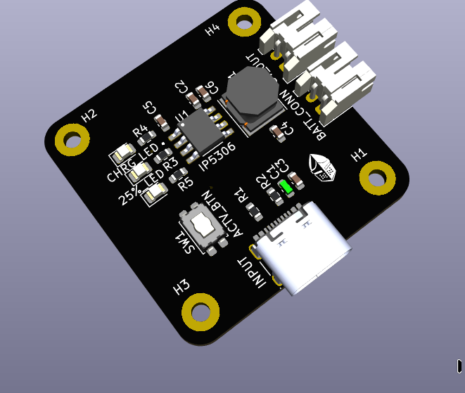 | 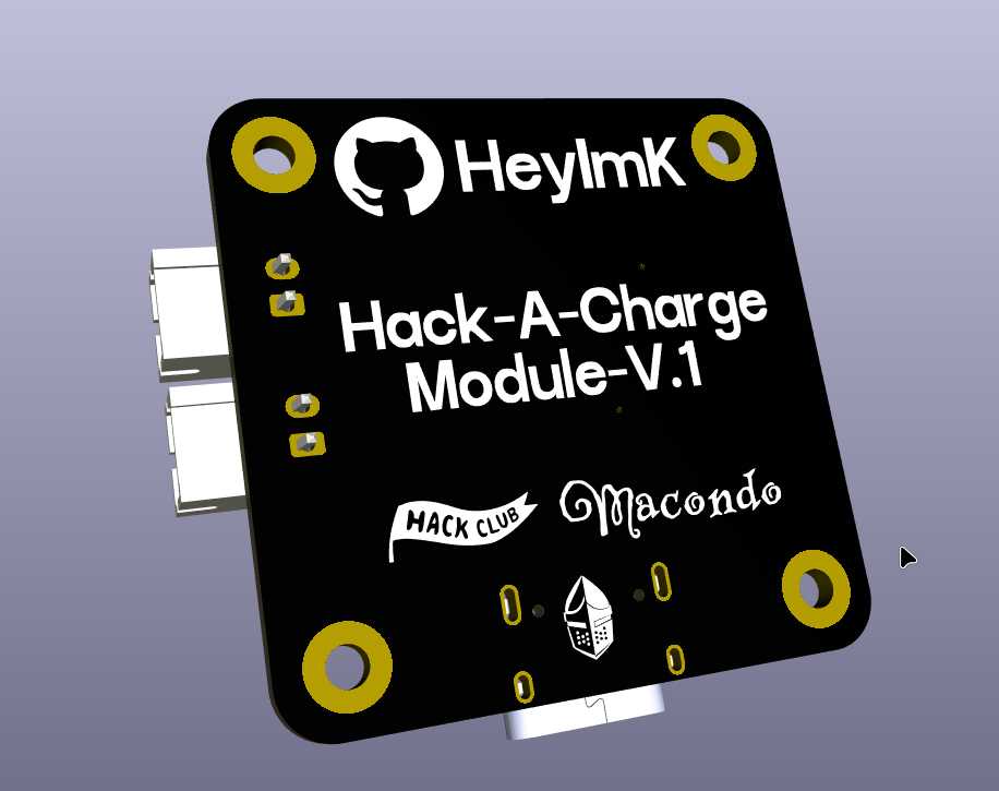 |
| Circuit Schematic Design |
|---|
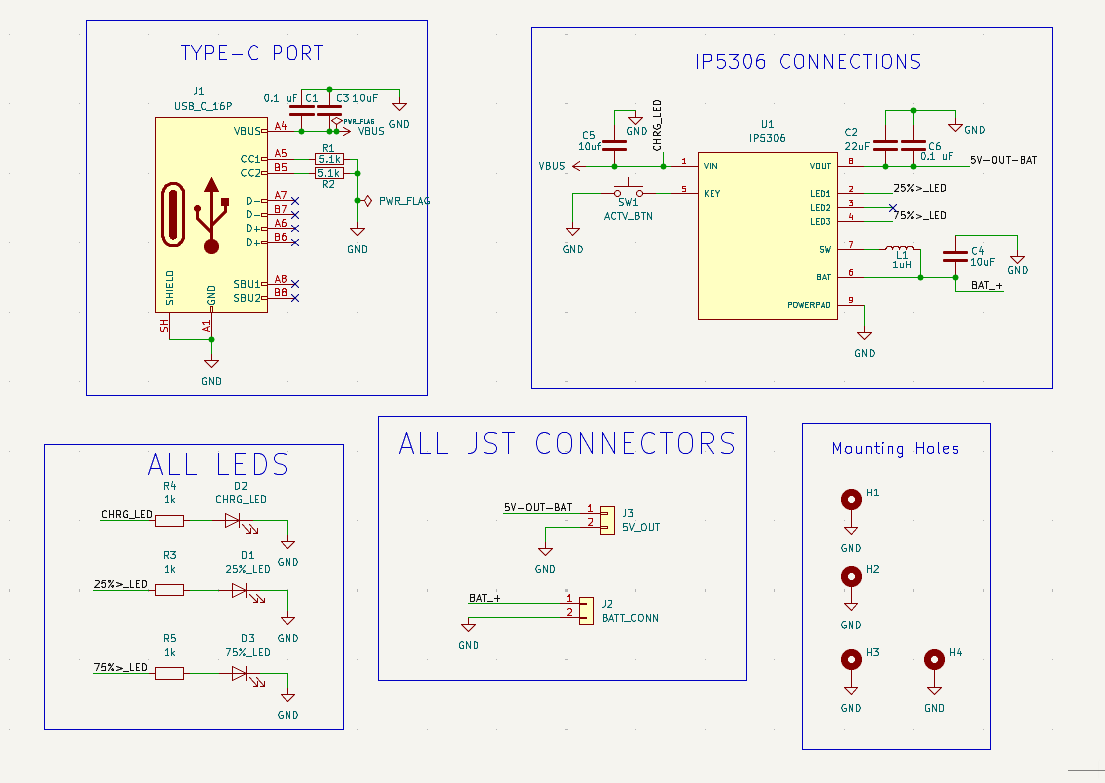 |
| PCB Top Layer Routing | PCB Bottom Layer Routing |
|---|---|
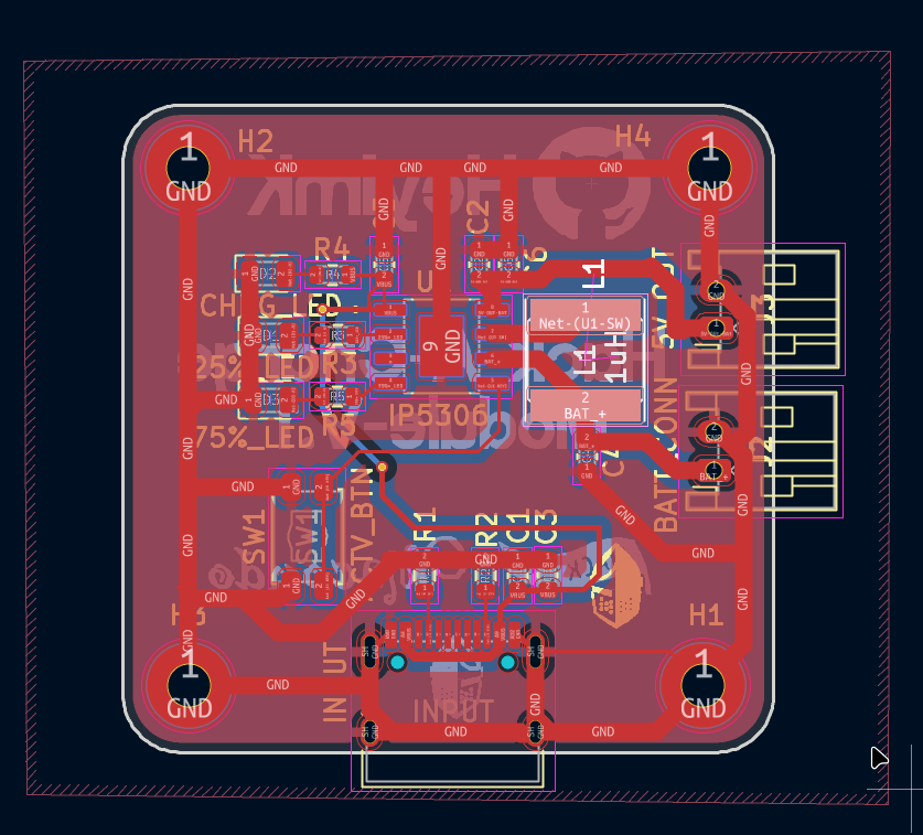 | 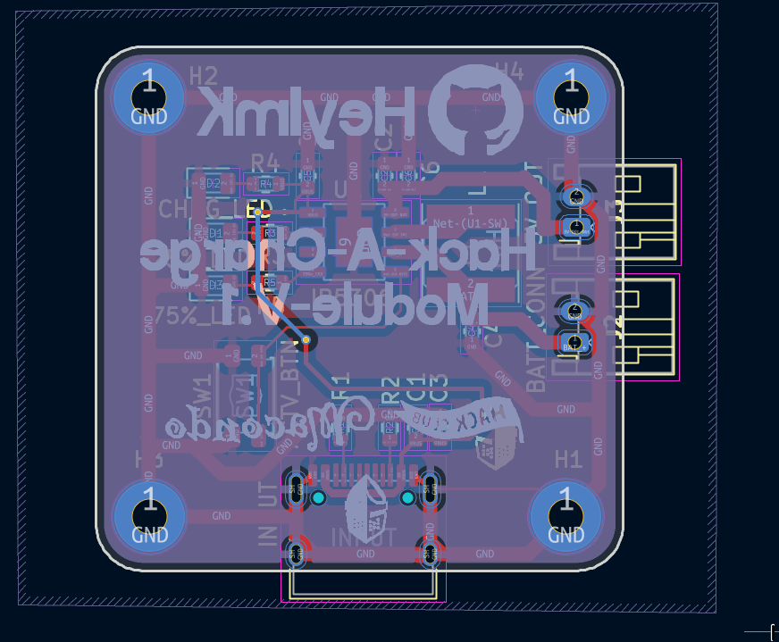 |
This hardware project is open-source and licensed under the CERN Open Hardware Licence Version 2 - Strongly Reciprocal (CERN-OHL-S-2.0).
You are free to copy, modify, distribute, and manufacture this board for personal or commercial use. However, if you modify these schematic or layout files and distribute your new design, you must release those modifications under this exact same CERN-OHL-S-2.0 license.
This design is shared without any warranty or implied guarantee. Check the LICENSE file for the full legal text.
| Qty | Value | Footprint | References |
|---|---|---|---|
| 8 | LOGO | LOGO | G***, G***, G***, G***, G***, G***, G***, G*** |
| 4 | Mount | MountingHole:MountingHole_2.2mm_M2_Pad | H1, H2, H3, H4 |
| 3 | 1k | Resistor_SMD:R_0603_1608Metric | R3, R4, R5 |
| 2 | 0.1 uF | Capacitor_SMD:C_0603_1608Metric | C1, C6 |
| 2 | 10uF | Capacitor_SMD:C_0603_1608Metric | C3, C4 |
| 2 | 5.1k | Resistor_SMD:R_0603_1608Metric | R1, R2 |
| 1 | 10uf | Capacitor_SMD:C_0603_1608Metric | C5 |
| 1 | 1uH | Inductor_SMD:L_Taiyo-Yuden_NR-60xx | L1 |
| 1 | 22uF | Capacitor_SMD:C_0603_1608Metric | C2 |
| 1 | 25%_LED | LED_SMD:LED_0805_2012Metric | D1 |
| 1 | 5V_OUT | Connector_JST:JST_PH_S2B-PH-K_1x02_P2.00mm_Horizontal | J3 |
| 1 | 75%_LED | LED_SMD:LED_0805_2012Metric | D3 |
| 1 | ACTV_BTN | Button_Switch_SMD:SW_SPST_EVQP2_ShortPushTravel_H2.1mm | SW1 |
| 1 | BATT_CONN | Connector_JST:JST_PH_S2B-PH-K_1x02_P2.00mm_Horizontal | J2 |
| 1 | CHRG_LED | LED_SMD:LED_0805_2012Metric | D2 |
| 1 | IP5306 | IP5306:SOP127P600X165-9N | U1 |
| 1 | USB_C_16P | Connector_USB:USB_C_Receptacle_HRO_TYPE-C-31-M-12 | INPUT |
It measures 33.9 × 33.7 mm and has 2 copper layers, 1.6 mm thick.
32 parts, built around the IP5306. The full list of its parts is on this page, with links to each part's symbol and footprint where PCBKit's library has them.
From the thesiliconknight/Hack-A-Charge-Module repository on GitHub, at the commit this page was made from: the board is SRC/battery module.kicad_pcb and its schematic SRC/battery module.kicad_sch. PCBKit opens the board in the browser, with nothing to install.
Its repository publishes it under the CERN-OHL-S-2.0 licence: you may reuse it on that licence's terms (keep the author's notice, and for a copyleft licence share your changes alike).

sh123/esp32_loraprs
LoRa ESP32 KISS Bluetooth modem (for APRSDroid or aprs.fi iOS) + APRS-IS RX/TX iGate over WiFi + Digipeater + DV (with Codec2 Walkie-Talkie)

BitDogLab/BitDogLab
Open-source educational hardware for embedded systems, programming, electronics, and physical computing.


LakoMoor/open-pocket-gbc
Game Boy / Game Boy Color on the Sipeed Tang Nano 20K: HDMI, Pocket-style menu, ST7735 LCD, USB remote. Open-source FPGA toolchain only.


Reiko0908/NeuralNetwork_Based_AutonomousCar
This project focuses on developing an autonomous car system powered by neural networks (NN). It utilizes deep learning techniques to enable key functionalities such as perception, path planning, and control.