2 layers82 × 38 mm
 therocketmoose/Thrust-Vecotring-System-For-Model-Rockets
Thrust Vectoring & Landing Control System for Model Rockets
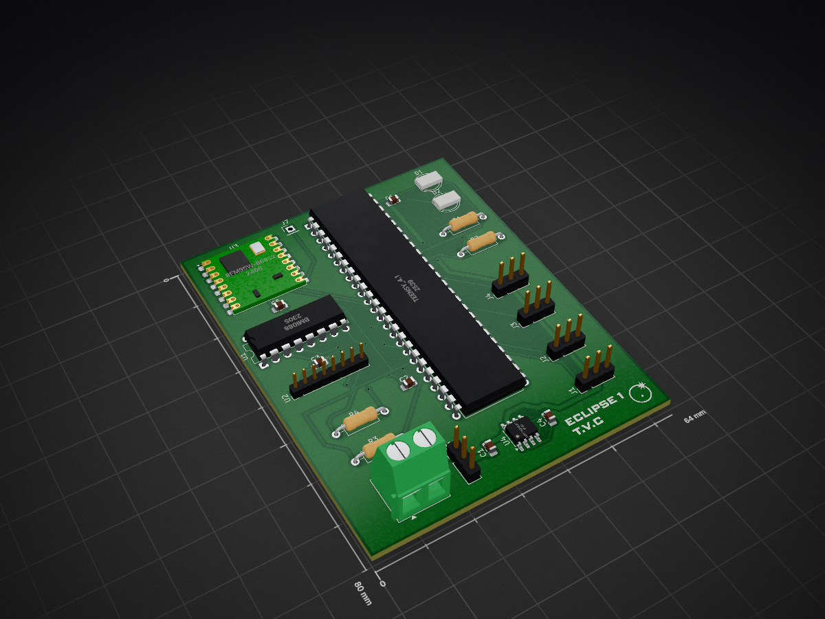
PCB Schematic Eclipse 1 is an open-source printed circuit board by therocketmoose, from the therocketmoose/Thrust-Vecotring-System-For-Model-Rockets repository on GitHub. It is a 2-layer board of 64 × 80 mm with 25 parts on 87 nets, routed with 185 tracks and 27 vias.
It is built around the TEENSY 4.1, MS5611-01BA03 and ADP7142ARDZ-3.3, with the BMI088 and RFM95W-868S2 among its other parts. Its parts include 7 connectors, 6 capacitors, 5 ICs, 4 resistors and 2 diodes. It belongs with the NXP (LPC, Kinetis, i.MX RT) boards of this library.


Thrust Vectoring & Landing Control System for Model Rockets
Lead Engineer: Xavier Vimard Project Start: 27/09/2025 Expected Completion: 20/05/2026
Project Overview:
This repository contains the full development of a thrust-controlled landing system (TCLS) for a model rocket platform. The project aims to design, build, and test a reusable model rocket capable of performing controlled ascent, attitude stabilization, descent management, and soft landing. The objective is to create a working proof-of-concept that integrates thrust vectoring, aerodynamic control, reaction wheel stabilization, and deployable landing legs into a unified flight system. This project is expected to operate over a one-year development window, with several intermediate prototypes and test campaigns.
The rocket platform itself is not the primary focus, the emphasis is the TCLS hardware, control algorithms, and validation testing necessary to achieve reliable vertical landing.
Project Goals:
Develop a fully functional thrust vectoring system capable of four-axis gimbal control for ascent and landing.
Implement a stability assist system using grid fins to manage minor deviations during ascent.
Design a reaction wheel to counter roll and maintain thrust vector orientation. as roll stabilization is critical, as uncontrolled roll makes TVC ineffective.
Engineer deployable landing legs to ensure stable recovery after touchdown.
Build a complete electronics and software stack integrating sensors, control logic, and closed-loop PID stabilization.
Validate feasibility via simulation, static fire testing, and full-scale launch tests.
Development Timeline:
My project follows a structured month-by-month roadmap:
System Architecture Core Components:
MCU: Teensy 4.1 — selected for deterministic real-time control performance.
IMU: Bosch BMI088 — optimized for high-vibration flight profiles.
Barometer: MS5611 — high-resolution altitude tracking (10 cm).
Ground Sation: ESP32 and Lora reciever — supplementary system for communication and logging.
Structure: Carbon fiber body, TVC gimbal, electronics bay, reaction wheel assembly.
CAD & Mechanical: The CAD design includes
A 4-axis servo-driven TVC module.
A compact reaction-wheel chamber below the nose cone.
A payload bay positioned directly above the TVC to avoid cable latency.
Simulation Work
To validate feasibility, ascent and landing behavior is simulated using Xcos (SciLab). Simulations include gyro stabilization behavior, ascent velocity and altitude curves, and TVC response testing. Early results indicate stable linear altitude growth and adequate thrust-to-weight margin, confirming the motor’s suitability for controlled ascent.
| Qty | Value | Footprint | References |
|---|---|---|---|
| 5 | Conn_01x03 | Connector_PinHeader_2.54mm:PinHeader_1x03_P2.54mm_Vertical | J1, J2, J3, J4, J6 |
| 4 | C | Capacitor_SMD:C_0805_2012Metric_Pad1.18x1.45mm_HandSolder | C2, C3, C5, C6 |
| 4 | R | Resistor_THT:R_Axial_DIN0207_L6.3mm_D2.5mm_P10.16mm_Horizontal | R1, R2, R3, R4 |
| 2 | C_Polarized | Capacitor_SMD:C_0805_2012Metric_Pad1.18x1.45mm_HandSolder | C1, C4 |
| 2 | LED | LED_THT:LED_D5.0mm | D1, D2 |
| 1 | ADP7142ARDZ-3.3 | Package_SO:SOIC-8-1EP_3.9x4.9mm_P1.27mm_EP2.29x3mm | U4 |
| 1 | BMI088 | Package_DIP:DIP-16_W7.62mm | U1 |
| 1 | Conn_01x01_Pin | Connector_PinHeader_2.54mm:PinHeader_1x01_P2.54mm_Vertical | J7 |
| 1 | Conn_01x02_Pin | TerminalBlock_Phoenix:TerminalBlock_Phoenix_MKDS-1,5-2-5.08_1x02_P5.08mm_Horizontal | J5 |
| 1 | LOGO | LOGO | . |
| 1 | MS5611-01BA03 | Connector_PinHeader_2.00mm:PinHeader_1x08_P2.00mm_Vertical | U2 |
| 1 | RFM95W-868S2 | RF_Module:HOPERF_RFM9XW_SMD | U3 |
| 1 | TEENSY_4.1 | Package_DIP:DIP-48_W15.24mm | IC1 |

jhns-de/70MHz-Soil-Sensor
Soil moisture and electrical conductivity (EC) sensor based on 70 MHz impedance measurement, developed as part of my master’s thesis.

LouisVizard/NavBoard
A full navigation solution featuring MCU, GNSS receiver, RF transceiver, and 9-DOF IMU


sutyazz/Resume-Projects
A comprehensive collection of engineering and computer science projects demonstrating expertise across multiple domains including embedded systems, web development, machine learning, signal processing, and hardware…

Tinkerbug-Robotics/TinkerRocket
Model rocket flight computer, ground station, iOS app, and simulation

mahdi-kh1265/780nm-ecdl-electronics
Control, interface, piezo-actuation, and power electronics for POSM's 780 nm Littrow external-cavity diode laser.

Terrapin-Rocket-Team/SRAD-Avionics
Code and PCBs for the avionics subteam for the SRAD flight computer and side projects
It measures 64 × 80 mm and has 2 copper layers, 1.6 mm thick.
25 parts, built around the TEENSY 4.1, MS5611-01BA03, ADP7142ARDZ-3.3 and BMI088. The full list of its parts is on this page, with links to each part's symbol and footprint where PCBKit's library has them.
From the therocketmoose/Thrust-Vecotring-System-For-Model-Rockets repository on GitHub, at the commit this page was made from: the board is PCB/PCB Schematic Eclipse 1/PCB Schematic Eclipse 1.kicad_pcb and its schematic PCB/PCB Schematic Eclipse 1/PCB Schematic Eclipse 1.kicad_sch. PCBKit opens the board in the browser, with nothing to install.
Its repository states no licence, so its author keeps all rights: ask therocketmoose before reusing the design.