Skip to the content
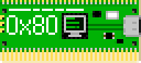
2 layers27.2 × 51.1 mmRemote, the printed circuit board in 3D

RPi Pico based POST (Power-On Self Test) Diagnostic Card

Size
27.2 × 51.1 mm
Copper layers
2
Thickness
1.6 mm
Parts
6
Nets
9
Pads
27
Tracks, vias
33, 1
Pours
2
Routed
Yes
KiCad
KiCad 6 (file 20211014)
Created
17 Jun 2022
Updated
7 Oct 2025

Overview

Remote is an open-source printed circuit board by TheRetroWeb, from the TheRetroWeb/PicoPOST repository on GitHub. It is a 2-layer board of 27.2 × 51.1 mm with 6 parts on 9 nets, routed with 33 tracks and 1 via.

Its parts include 3 switches, 2 connectors and 1 resistor.

README

README.md

PicoPOST

[!NOTE] You can get a quick summary from the blog post! Introducing the PicoPOST - The Retro Web Blog

Introduction

PicoPOST Logo

PicoPOST is a PC diagnostic card for systems with, at least, an 8-bit ISA slot. It's based around the Raspberry Pi Pico, powered by an RP2040.

PicoPOST is designed to provide many additional benefits over the basic POST cards that are commonly available from Chinese vendors on eBay and other sites.

This project is getting ready for public usage, with a few prototypes already in use for development purposes. More information soon as it gets finalized.

Implemented features

  • Simple user interface, with a graphical monochrome 128x32 OLED display and a few buttons living on their own remote control
  • Port 80h readout, with 4-place output history
  • Port 90h readout, for IBM PS/2s
  • Port 84h reaodut, for Compaq machines*
  • Port 300h readout, for some EISA systems*
  • Port 378h readout, for some Olivetti machines*
  • More complete bus activity dumping facility
  • Reset pulse detection
  • +5V and +12V and -12V voltage monitor**
  • Display is dimmed after 15s of inactivity to mitigate burn-in
  • Flying Toasters! screensaver after 30s of inactivity on the main menu

*: We don't have a specimen handy, so we need confirmation from someone else out there.
**: Negative voltages into a positive ADC is too much mental gymnastics without additional hardware

Videos

We are slowly compiling a YouTube playlist with a whole bunch of demonstration pieces, showing what the PicoPOST is capable of doing.
Stay tuned for more content!

Wishlist

New features have been implemented with the new rev 6 PCB and matching firmware.

  • Full bus activity trace (HW OK, FW provisioned, but we need to make sure we are not missing data)
  • Bus clock reader (HW OK, FW TBD)
  • ... anything else, as long as the hardware allows it and someone implements it in firmware

Building the firmware

Automagically

We make use of Visual Studio Code and the official Raspberry Pi Pico extension for an easier life. When you first open the project in VSCode, you will be prompted to install a few suggested extensions; accept the proposal and follow on-screen instructions.

You should now be greeted by the CMake and Pi Pico sidebar panels. Use the CMake panel to switch between Debug or Release builds, then refer to the Pico panel for building, uploading, and debugging the firmware.

It's already set up to probe for a compatible debugger via OpenOCD and gdbserver, and it works really well with our official Raspberry Pi Debug Probe. I expect other SWD debuggers to work just as well (J-Link, STLink, ...).

Manually

The firmware is built using the official Raspberry Pi RP2040 SDK. Follow the official documentation for setting it up.

The procedure is pretty straight-forward:

  1. Clone the repo
    text
    mkdir ~/repo
    cd ~/repo
    git clone https://github.com/TheRetroWeb/PicoPOST
  2. Enter the repo and initialize it
    text
    cd PicoPOST
    git submodule init
    git submodule update
  3. Prepare the build system with CMake
    text
    export PICO_SDK_PATH /path/to/pico/sdk
    cmake -DCMAKE_EXPORT_COMPILE_COMMANDS:BOOL=TRUE \
        -DCMAKE_BUILD_TYPE:STRING=Release \
        -DCMAKE_C_COMPILER:FILEPATH=/usr/bin/arm-none-eabi-gcc \
        -DCMAKE_CXX_COMPILER:FILEPATH=/usr/bin/arm-none-eabi-g++ \
        -S./firmware \
        -B./build \
        -G "Unix Makefiles"
  4. Build the firmware
    text
    cmake --build ./build --config Release --target all -j $(nproc)

Customize the firmware

There are a couple of details you might want to tune at compile time. More specifically, you may want to better calibrate the voltage monitor to show more accurate results.

In the primary firmware\CMakeLists.txt file, there are three variables you can set to skew the final ADC conversion result. These were added to account for resistor tolerances in the voltage divider circuits.

  • CALIBADJ_5V, correction factor for the +5V rail
  • CALIBADJ_12V, correction factor for the +12V rail

Calculating these factors is pretty straight forward:

  • Install the default firmware
  • Connect PicoPOST to your computer of choice with a known good power supply
  • Enter Voltage Monitor mode
  • Turn on the computer
  • With a multimeter, measure the rail voltage as close as possible to PicoPOST
  • Compute the required calibration factor by dividing the measured value with the one shown by PicoPOST
  • Edit the CALIBADJ variable and build the firmware again

Flashing the firmware

  1. In order to load new firmware, the Pico must be booted into UF2 mode:
    • If the board is powered off, keep the BOOTSEL button pressed while plugging the USB cable into the Pico itself.
    • If the board is already powered, you can short the "Pico Reset" pins on the back of the card instead of removing the USB cable.
    • Alternatively, if the board is powered via USB from a PC with a data cable, you can move to the Update FW menu entry. By pressing Enter, the Pico will then be rebooted into UF2 mode automatically.
  2. A mass storage device should be now mounted on your computer.
  3. Drag and drop (or copy and paste) the .uf2 firmware file into the device.
  4. Once loaded, it will automatically restart and disconnect.
  5. If all went well, you should now be greeted by the main menu on the OLED display.
    You can verify the current firmware version by entering the Info page.

Interested in helping?

Directories

text
datasheets/  Reference documentation for components used in the PicoPOST
firmware/    Source code for the PicoPOST firmware (written in C/C++ with the official Pico SDK)
pcb/         KiCad schematics and PCB design files

License

The firmware portion of PicoPOST is licensed under the MIT license.
The hardware portion of PicoPOST is licensed under the CERN OHL v2 Permissive license.

Parts

6
QtyValueFootprintReferences
11000Resistor_SMD:R_1206_3216Metric_Pad1.30x1.75mm_HandSolderR13
1DownButton_Switch_THT:SW_PUSH_6mm_H5mmSW2
1OLED hereConnector_PinSocket_2.54mm:PinSocket_1x05_P2.54mm_VerticalJ4
1Select/MenuButton_Switch_THT:SW_PUSH_6mm_H5mmSW3
1UpButton_Switch_THT:SW_PUSH_6mm_H5mmSW1
1remote headerConnector_PinSocket_2.54mm:PinSocket_1x08_P2.54mm_VerticalJ3

More from TheRetroWeb/PicoPOST

10
  • 4 layers102.6 × 107.3 mmPro rev1, the printed circuit board in 3D

    Pro rev1

    TheRetroWeb/PicoPOST

    RPi Pico based POST (Power-On Self Test) Diagnostic Card

    136 parts58
  • 2 layers99.6 × 69.2 mmISA rev8, the printed circuit board in 3D

    ISA rev8

    TheRetroWeb/PicoPOST

    RPi Pico based POST (Power-On Self Test) Diagnostic Card

    45 parts58
  • 2 layers109 × 51.1 mmISA rev4, the printed circuit board in 3D

    ISA rev4

    TheRetroWeb/PicoPOST

    RPi Pico based POST (Power-On Self Test) Diagnostic Card

    38 parts58
  • 2 layers82 × 68.3 mmISA rev6, the printed circuit board in 3D

    ISA rev6

    TheRetroWeb/PicoPOST

    RPi Pico based POST (Power-On Self Test) Diagnostic Card

    37 parts58
  • 2 layers81.5 × 51.1 mmISA rev5, the printed circuit board in 3D

    ISA rev5

    TheRetroWeb/PicoPOST

    RPi Pico based POST (Power-On Self Test) Diagnostic Card

    35 parts58
  • 2 layers81.3 × 87.6 mmISA card rev2, the printed circuit board in 3D

    ISA card rev2

    TheRetroWeb/PicoPOST

    RPi Pico based POST (Power-On Self Test) Diagnostic Card

    28 parts58
  • 2 layers86.4 × 108.6 mmISA card rev1, the printed circuit board in 3D

    ISA card rev1

    TheRetroWeb/PicoPOST

    RPi Pico based POST (Power-On Self Test) Diagnostic Card

    25 parts58
  • 2 layers50 × 50 mmRemote, the printed circuit board in 3D

    Remote

    TheRetroWeb/PicoPOST

    RPi Pico based POST (Power-On Self Test) Diagnostic Card

    25 parts58
  • 2 layers50 × 50 mmRemote, the printed circuit board in 3D

    Remote

    TheRetroWeb/PicoPOST

    RPi Pico based POST (Power-On Self Test) Diagnostic Card

    22 parts58
  • 2 layers50 × 50 mmRemote, the printed circuit board in 3D

    Remote

    TheRetroWeb/PicoPOST

    RPi Pico based POST (Power-On Self Test) Diagnostic Card

    21 parts58

Similar boards

  • 2 layers18.5 × 11.1 mmSwitch, the printed circuit board in 3D

    Switch

    byrantech/laptop

    anyon_e, a highly integrated, high end, open source laptop. Attempt the impossible.

    6 parts4.3kMIT
  • 2 layers14.6 × 33 mmBrain board SD Card 1, the printed circuit board in 3D

    Brain board SD Card 1

    rusefi/rusefi

    rusefi - GPL internal combustion engine control unit

    6 parts1.2k
  • 2 layers9 × 9 mmDpoint, the printed circuit board in 3D

    Dpoint

    Jcparkyn/dpoint

    Open-source digital stylus using camera tracking and inertial measurements

    6 parts1.1kMIT
  • 2 layers51.5 × 16.6 mmMicroswitchXY Endstop, the printed circuit board in 3D

    MicroswitchXY Endstop

    VoronDesign/Voron-Hardware

    Cool Hardware designed by the Voron Design group

    6 parts1.1kGPL-3.0
  • 2 layers21.9 × 76.7 mmAmiga External, the printed circuit board in 3D

    Amiga External

    hoglet67/RGBtoHDMI

    Bare-metal Raspberry Pi project that provides pixel-perfect sampling of Retro Computer RGB/YUV video and conversion to HDMI

    6 parts1kGPL-3.0
  • 2 layers88.9 × 50.8 mmBusinesscard, the printed circuit board in 3D

    Businesscard

    hackclub/OnBoard

    💡 Join 1,000 teenagers and make your first PCB with a $100 grant!

    6 parts915
  • 2 layers20.3 × 15.2 mmL0 RGB led, the printed circuit board in 3D

    L0 RGB led

    Luos-io/luos_engine

    Open-source and real-time orchestrator for cyber-physical-systems, to easily design, test and deploy embedded applications and digital twins.

    6 parts546MIT
  • 2 layers9 × 3.6 mmOpticalEncoder, the printed circuit board in 3D

    OpticalEncoder

    adamb314/ServoProject

    Getting the most out of your hobby servo

    6 parts545

Questions

How big is the Remote PCB?

It measures 27.2 × 51.1 mm and has 2 copper layers, 1.6 mm thick.

What parts does the Remote use?

6 parts. The full list of its parts is on this page, with links to each part's symbol and footprint where PCBKit's library has them.

Where can I download the Remote KiCad files?

From the TheRetroWeb/PicoPOST repository on GitHub, at the commit this page was made from: the board is pcb/ISA rev5/remote.kicad_pcb and its schematic pcb/ISA rev1/ISA card rev1.kicad_sch. PCBKit opens the board in the browser, with nothing to install.

Can I use the Remote design in my own project?

Its repository states no licence, so its author keeps all rights: ask TheRetroWeb before reusing the design.