2 layers38.9 × 16.5 mm
LPC824 RFM9x
jdesbonnet/RFMxx_LPC812_PCB
PCB board to experiment with HopeRF RFM69 and RFM98 radio modules. Uses ARM Cortex-M0+ LPC812 as controller.
16 parts4

 therealprof/MOA-R-B3
The mother of all Rust boards
MOA R B is an open-source printed circuit board by therealprof, from the therealprof/MOA-R-B repository on GitHub, published under the BSD-3-Clause licence. It is a 2-layer board of 91.4 × 99.1 mm with 53 parts on 139 nets, routed with 692 tracks and 416 vias.
It is built around the LPC824M201JDH20, MIC5504-3.3YM5 and USBLC6-2SC6. Its parts include 13 capacitors, 13 connectors, 9 resistors, 9 diodes and 6 ICs. It belongs with the interfaces and adapters boards and the STM32, SAM D and SAM and NXP (LPC, Kinetis, i.MX RT) boards of this library.


The MOA(R)B is a proof of concept proto board which breaks out 4 MCUs from different vendors which are readily supported by the Rust programming language and adds a DAP42 USB debugger/programmer with virtual serial port as well as the requisite USB port and voltage regulator for good measure.
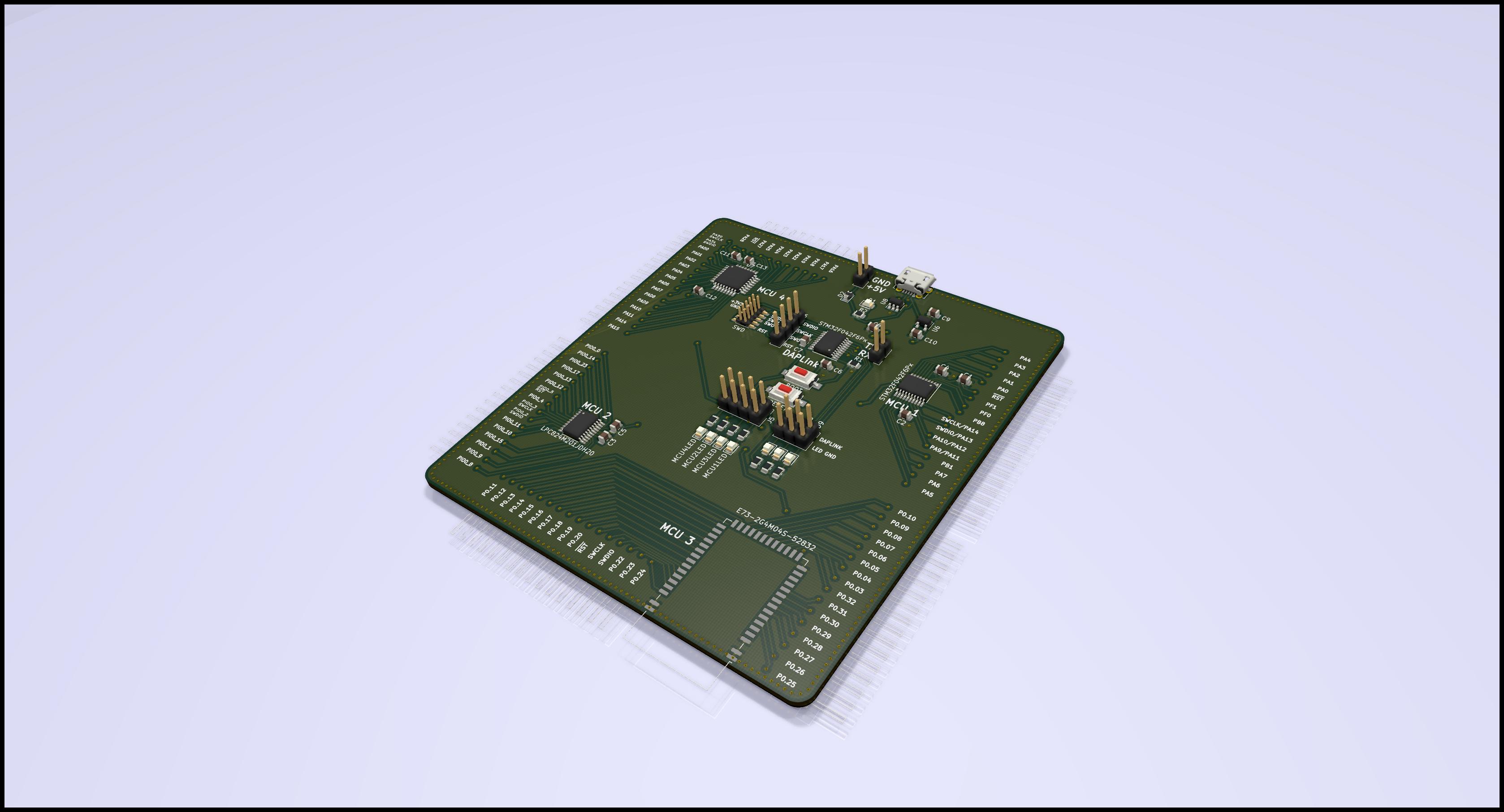
The MOA(R)B was developed to demonstrate how easy it is to design and manufacture Rust-able microcontroller designs. The original plan was to give a talk about this at Oxidize 2019 but that didn't happen. The board is still the first iteration (with a minor fix applied) and I don't expect to further update it. However feel free to take the full or parts of the design and do whatever you want with it.
The following MCUs are supported (but compatible footprints might be used as well):
In addition another STM32F042F6P6 can be populated as DAPlink compatible debugger/programmer with virtual serial port.
I've included an interactive HTML BOM and population guide here.
NOTE: If you happen to have one of the 10 first run boards you will need to add a shame wire from pad 15 of the DAPlink MCU to ground -- if you want to populate and use the onboard debugger, that is. If you work with the published version 1.1 there're no known errata.
Absolutely, everything is licensed under the BSD license so please go ahead and use it however you'd like.
| Qty | Value | Footprint | References |
|---|---|---|---|
| 11 | 100n | Capacitor_SMD:C_0805_2012Metric | C1, C2, C3, C4, C5, C6, C7, C8, C11, C12, C13 |
| 8 | 470 | Resistor_SMD:R_0805_2012Metric | R2, R3, R4, R5, R6, R7, R8, R9 |
| 2 | 1µ | Capacitor_SMD:C_0805_2012Metric | C9, C10 |
| 2 | STM32F042F6Px | Package_SO:TSSOP-20_4.4x6.5mm_P0.65mm | U1, U3 |
| 1 | 10k | Resistor_SMD:R_0805_2012Metric | R1 |
| 1 | ATSAMD21E15A | Package_QFP:TQFP-32_7x7mm_P0.8mm | ATSAMD21E15 |
| 1 | BOOT | Button_Switch_SMD:SW_SPST_CK_RS282G05A3 | SW2 |
| 1 | Conn MCU 1 | Connector_Harwin:Harwin_M20-89017xx_1x17_P2.54mm_Horizontal | J2 |
| 1 | Conn MCU 2 | Connector_Harwin:Harwin_M20-89016xx_1x16_P2.54mm_Horizontal | J1 |
| 1 | Conn MCU 3_1 | Connector_Harwin:Harwin_M20-89016xx_1x16_P2.54mm_Horizontal | J8 |
| 1 | Conn MCU 3_2 | Connector_Harwin:Harwin_M20-89016xx_1x16_P2.54mm_Horizontal | J11 |
| 1 | Conn MCU 4_1 | Connector_Harwin:Harwin_M20-89016xx_1x16_P2.54mm_Horizontal | J10 |
| 1 | Conn MCU 4_2 | Connector_Harwin:Harwin_M20-89011xx_1x11_P2.54mm_Horizontal | J12 |
| 1 | Conn Power | Connector_PinHeader_2.54mm:PinHeader_2x04_P2.54mm_Vertical | J5 |
| 1 | D | Diode_SMD:D_0805_2012Metric | D2 |
| 1 | E73-2G4M04S-52832 | RF_Module:E73-2G4M04S | U4 |
| 1 | LED0 | LED_SMD:LED_0805_2012Metric | D7 |
| 1 | LED1 | LED_SMD:LED_0805_2012Metric | D8 |
| 1 | LED2 | LED_SMD:LED_0805_2012Metric | D9 |
| 1 | LEDs | Connector_PinHeader_2.54mm:PinHeader_2x03_P2.54mm_Vertical | J4 |
| 1 | LPC824M201JDH20 | Package_SO:TSSOP-20_4.4x6.5mm_P0.65mm | U2 |
| 1 | MCU1LED | LED_SMD:LED_0805_2012Metric | D3 |
| 1 | MCU2LED | LED_SMD:LED_0805_2012Metric | D4 |
| 1 | MCU3LED | LED_SMD:LED_0805_2012Metric | D5 |
| 1 | MCU4LED | LED_SMD:LED_0805_2012Metric | D6 |
| 1 | MIC5504-3.3YM5 | Package_TO_SOT_SMD:SOT-23-5 | U6 |
| 1 | PWR IN | Connector_PinHeader_2.54mm:PinHeader_1x02_P2.54mm_Vertical | J7 |
| 1 | PWR LED | LED_SMD:LED_0805_2012Metric | D1 |
| 1 | RESET | Button_Switch_SMD:SW_SPST_CK_RS282G05A3 | SW1 |
| 1 | SWD | Connector_PinHeader_1.27mm:PinHeader_2x05_P1.27mm_Vertical_SMD | J3 |
| 1 | SWD | Connector_PinHeader_2.54mm:PinHeader_1x04_P2.54mm_Vertical | J6 |
| 1 | Serial | Connector_PinHeader_2.54mm:PinHeader_1x02_P2.54mm_Vertical | J13 |
| 1 | USBLC6-2SC6 | Package_TO_SOT_SMD:SOT-23-6 | U8 |
| 1 | USB_B_Micro | Connector_USB:USB_Micro-B_Molex-105017-0001 | J9 |
It measures 91.4 × 99.1 mm and has 2 copper layers, 1.6 mm thick.
53 parts, built around the LPC824M201JDH20, MIC5504-3.3YM5 and USBLC6-2SC6. The full list of its parts is on this page, with links to each part's symbol and footprint where PCBKit's library has them.
From the therealprof/MOA-R-B repository on GitHub, at the commit this page was made from: the board is MOA(R)B.kicad_pcb. PCBKit opens the board in the browser, with nothing to install.
Its repository publishes it under the BSD-3-Clause licence: you may reuse it on that licence's terms (keep the author's notice, and for a copyleft licence share your changes alike).
jdesbonnet/RFMxx_LPC812_PCB
PCB board to experiment with HopeRF RFM69 and RFM98 radio modules. Uses ARM Cortex-M0+ LPC812 as controller.

jdesbonnet/PCB_LPC824M201JDH20_breakout
Breakout board PCB for LPC824 in TSSOP20 package (LPC824M201JDH20, LPC822M101JDH20)


Squantor/squantorDevelBoards
Various development boards/test for microcontrollers, check for breakouts here


therealprof/MCUmeter-hardware
Kicad project files and gerbers for my MCUmeter project
