4 layers55 × 50 mm
 therealprof/MCUmeter-hardware6
Kicad project files and gerbers for my MCUmeter project
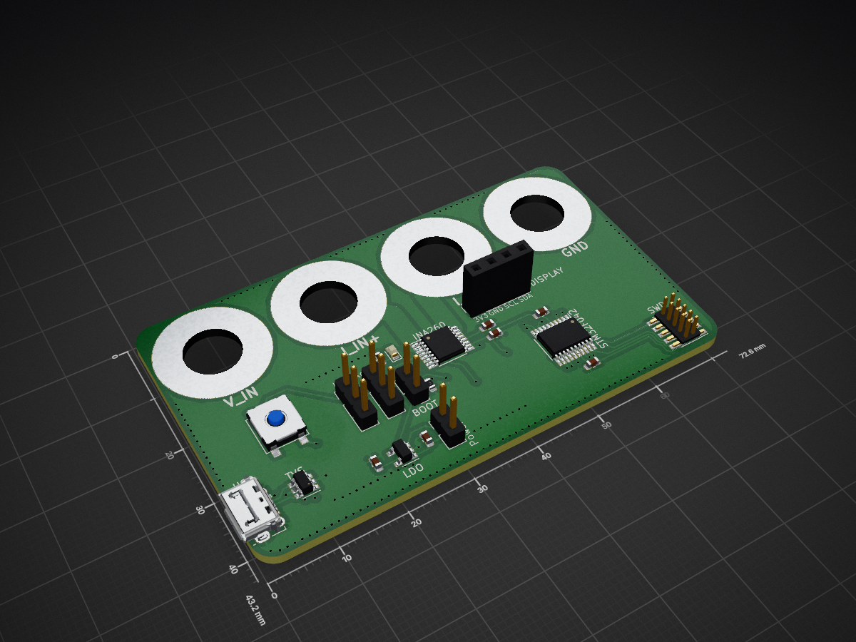
MCUmeter is an open-source printed circuit board by therealprof, from the therealprof/MCUmeter-hardware repository on GitHub, published under the BSD-3-Clause licence. It is a 2-layer board of 72.6 × 43.2 mm with 31 parts on 35 nets, routed with 282 tracks and 193 vias.
It is built around the MIC5504-3.3YM5 and USBLC6-2SC6. Its parts include 6 capacitors, 2 resistors, 2 connectors, 1 diode and 1 switch. It belongs with the STM32 boards of this library.


The MCUmeter started as a gift for a "secret santa" round at my favourite electronics club, the Boldport Club. It was something I always wanted to do because it's useful, simple to build and can offers a nice learning experience for people who want to do microcontroller based hardware themselves.
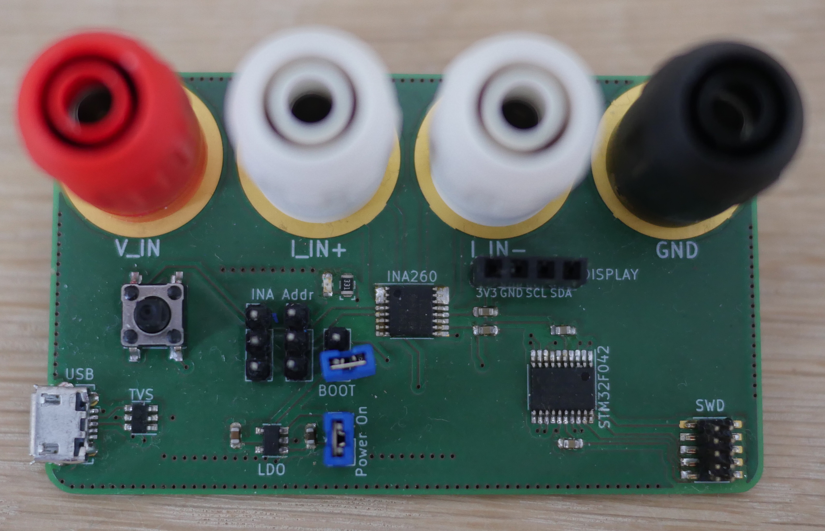
In a nutshell it’s a high performance voltage/current/power monitor which will render it’s voltags/current/power readings supplied by a Texas Instruments INA260 via a STM32F042 microcontroller onto a small OLED display.
It consists of two main ingredients:
The hardware design was done in KiCad and this repository contains both the KiCad 5 design files as well as the Gerber files which can be sent directly to a fab house to build the project, like the one I used for the prototypes. If you'd like you can order them directly from Aisler using this link.
This is what the boards look like: 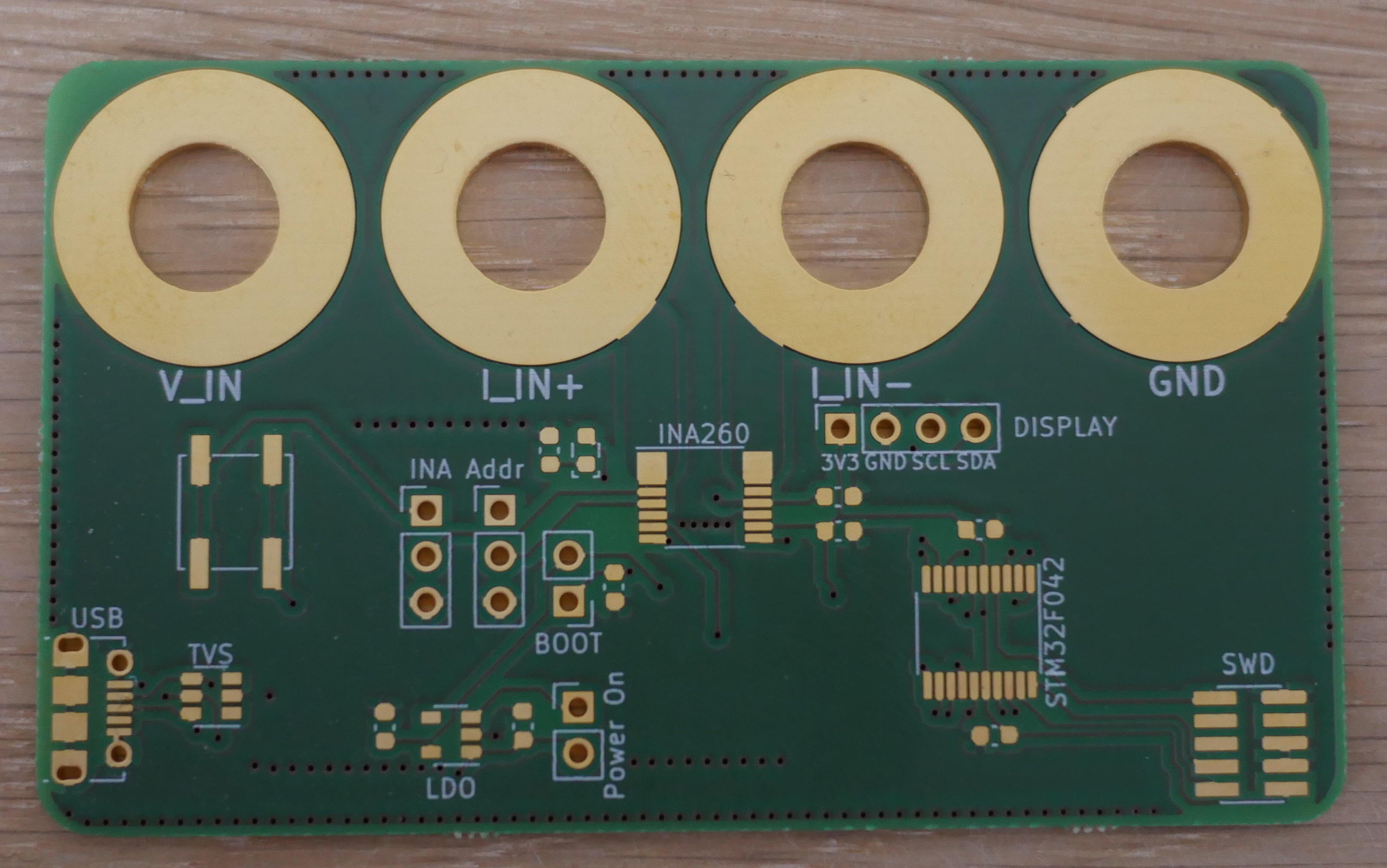 and
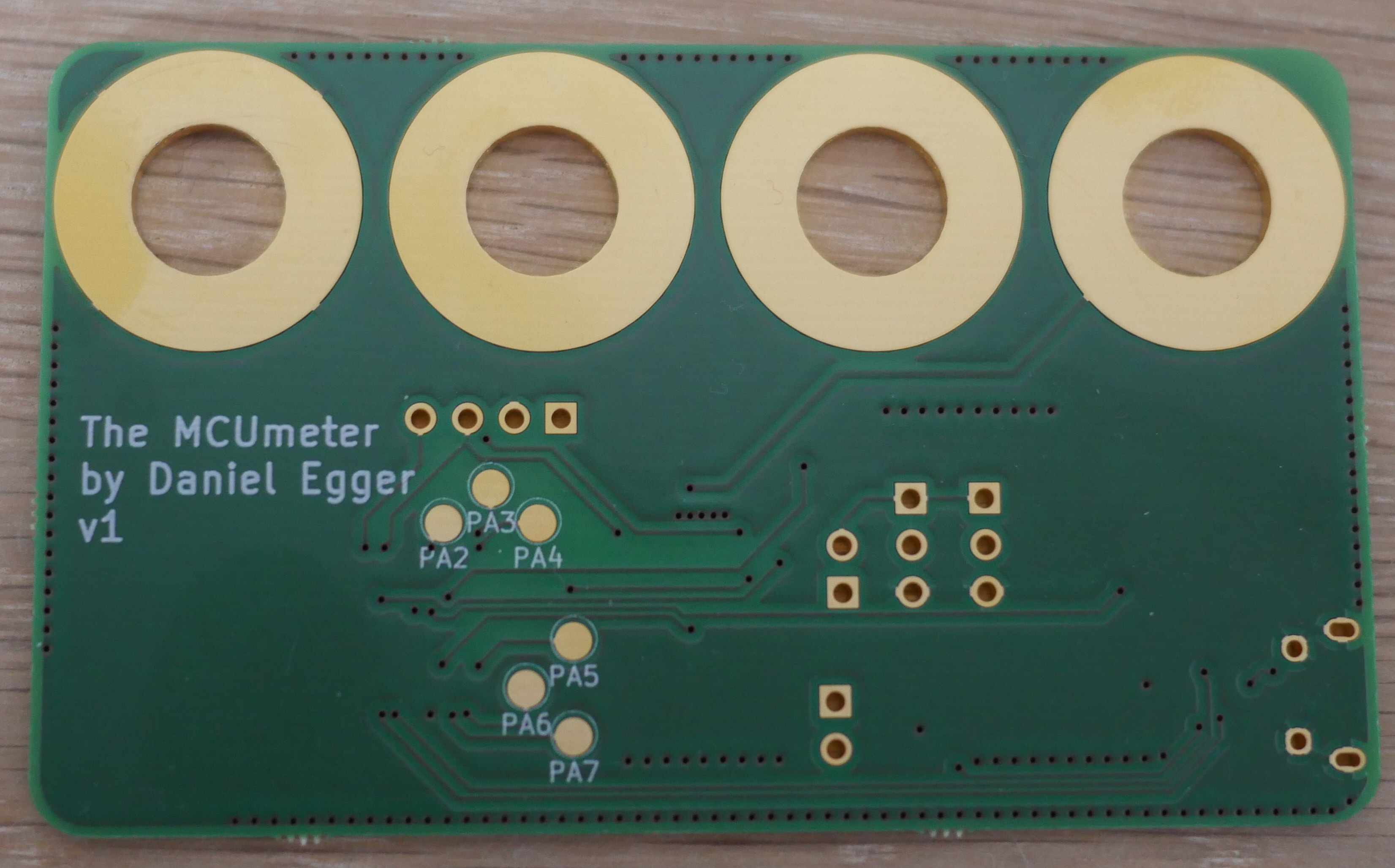
The INA260 allows sensing voltages (DC and positive values only!) up to 36V and high-side as well as low-side currenty (polarity not relevant). It can also do the power calculations, although at reduced precision.
The connections (from left to right) are
It also provides a 4-pin header to connect a SSD1306 OLED display with I2C interface using the following pinout:
The connectors can be either soldered onto the board or screwed on, good results have been achieved with e.g. MC/Stäubli XUB-G
Absolutely, everything is licensed under the BSD license so please go ahead and use it however you'd like.
| Qty | Value | Footprint | References |
|---|---|---|---|
| 6 | TestPoint | TestPoint:TestPoint_Pad_D2.0mm | PA2, PA3, PA4, PA5, PA6, PA7 |
| 4 | 100n | Capacitor_SMD:C_0603_1608Metric | C2, C3, C5, C6 |
| 4 | MountingHole_Pad | MountingHole:MountingHole_8.4mm_M8_Pad | H1, H2, H3, H4 |
| 2 | 1µ | Capacitor_SMD:C_0603_1608Metric | C1, C4 |
| 2 | Conn_01x02 | Connector_PinHeader_2.54mm:PinHeader_1x02_P2.54mm_Vertical | BOOT, J9 |
| 2 | Conn_01x03 | Connector_PinHeader_2.54mm:PinHeader_1x03_P2.54mm_Vertical | J5, J6 |
| 1 | 10k | Resistor_SMD:R_0603_1608Metric | R1 |
| 1 | 500R | Resistor_SMD:R_0603_1608Metric | R2 |
| 1 | Conn_01x04_Female | Connector_PinSocket_2.54mm:PinSocket_1x04_P2.54mm_Vertical | DISPLAY |
| 1 | Conn_ARM_JTAG_SWD_10 | Connector_PinHeader_1.27mm:PinHeader_2x05_P1.27mm_Vertical_SMD | SWD |
| 1 | INA260 | Package_SO:TSSOP-16_4.4x5mm_P0.65mm | INA260 |
| 1 | LED | LED_SMD:LED_0603_1608Metric | D1 |
| 1 | MIC5504-3.3YM5 | Package_TO_SOT_SMD:SOT-23-5 | LDO |
| 1 | STM32F042F6Px | Package_SO:TSSOP-20_4.4x6.5mm_P0.65mm | STM32F042 |
| 1 | SW_Push | Button_Switch_SMD:SW_SPST_EVPBF | SW1 |
| 1 | USBLC6-2SC6 | Package_TO_SOT_SMD:SOT-23-6 | TVS |
| 1 | USB_B_Micro | Connector_USB:USB_Micro-B_Molex-105017-0001 | USB |
It measures 72.6 × 43.2 mm and has 2 copper layers, 1.6 mm thick.
31 parts, built around the MIC5504-3.3YM5 and USBLC6-2SC6. The full list of its parts is on this page, with links to each part's symbol and footprint where PCBKit's library has them.
From the therealprof/MCUmeter-hardware repository on GitHub, at the commit this page was made from: the board is v1/MCUmeter.kicad_pcb. PCBKit opens the board in the browser, with nothing to install.
Its repository publishes it under the BSD-3-Clause licence: you may reuse it on that licence's terms (keep the author's notice, and for a copyleft licence share your changes alike).


ELEC70142-VLSI-Coursework/vlsi_test_platform
Validation environment for the VLSI SoC project. This repository integrates mechanical and PCB designs for a dedicated testrig with FPGA-based gateware and Python-driven software abstractions to facilitate full-chip…

krishchan007/DUT_Interface_board_v0.2
v0.2 of DUT interface board with significant changes in layout, architecture etc.


ajama0609/emg_hand_manipulation
emg HIL with arduino matlab manipulation of allegroHand