2 layers78 × 44 mm

 TheFlemoid/ESP-32-Stepper-Driver
PCB incorporating an ESP-WROOM-32 MCU with two DRV8825 stepper motor drivers.
Balance Bot is an open-source printed circuit board by TheFlemoid, from the TheFlemoid/ESP-32-Stepper-Driver repository on GitHub. It is a 4-layer board of 78 × 60 mm with 57 parts on 76 nets, routed with 634 tracks and 79 vias.
It is built around the CH340C, MMBT2222A and SSP1117-5.0V, with the TSSA5U50 and TYPE-C16PIN among its other parts. Its parts include 13 resistors, 12 capacitors, 11 connectors, 9 ICs and 4 diodes. It belongs with the robots and motor control boards and the ESP32 boards of this library.


PCB integrating an ESP-WROOM-32 microcontroller with two A4988/DRV8825 stepper motor drivers.
This is a four layer PCB that I originally designed this for an ESP-32 controlled, NEMA17 powered robot. However it can also be useful for any other application requiring microcontroller control, stepper motors, and any form of SPI or I2C peripheral.
Before connecting and driving the DRV8825, ensure that you set the current limit on both DRV8825/A4988 stepper drivers.
Features include:
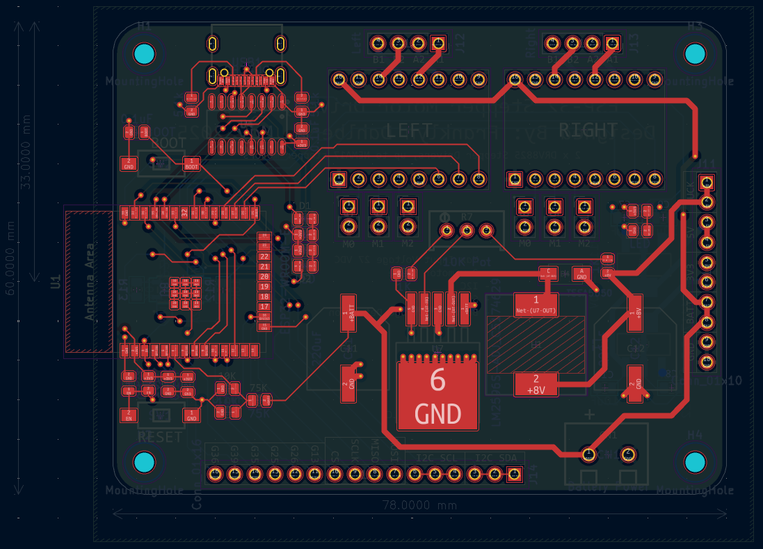
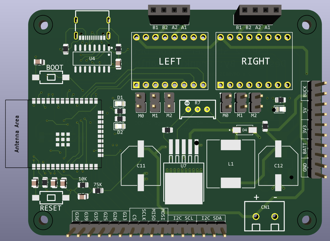
| Qty | Value | Footprint | References |
|---|---|---|---|
| 5 | 0.1uF | Capacitor_SMD:C_0805_2012Metric | C1, C2, C4, C5, C13 |
| 4 | 10K | Resistor_SMD:R_0805_2012Metric | R1, R11, R12, R13 |
| 4 | 10uF | Capacitor_SMD:C_0805_2012Metric | C3, C7, C9, C10 |
| 4 | MountingHole | MountingHole:MountingHole_2.5mm | H1, H2, H3, H4 |
| 3 | 1k | Resistor_SMD:R_0805_2012Metric | R2, R3, R4 |
| 3 | LED | LED_SMD:LED_0805_2012Metric | D1, D2, D3 |
| 2 | 1K | Resistor_SMD:R_0805_2012Metric | R5, R6 |
| 2 | 220uF | easyeda2kicad:CAP-SMD_BD10.0-L10.3-W10.3-LS11.3-FD | C11, C12 |
| 2 | 5.1k | Resistor_SMD:R_0805_2012Metric | R8, R9 |
| 2 | MMBT2222A | Snap_EDA:SOT23_FAS | U8, U9 |
| 1 | 100uH | Snap_EDA:IND_BOURNS_SRR1210 | L1 |
| 1 | 10K Pot | easyeda2kicad:RES-ADJ-TH_3P-L10.0-W10.0-P2.50-L | R7 |
| 1 | 22uF | Capacitor_SMD:C_0805_2012Metric | C8 |
| 1 | 75K | Resistor_SMD:R_0805_2012Metric | R10 |
| 1 | AMS1117-3.3_C347222 | easyeda2kicad:SOT-223-4_L6.5-W3.5-P2.30-LS7.0-BR | U5 |
| 1 | BOOT | easyeda2kicad:SW-SMD_L6.0-W3.3-LS8.0 | BOOT |
| 1 | Battery Power | easyeda2kicad:CONN-TH_2P-P5.00_MX126-5.0-GN01-02P-CU-S-A | CN1 |
| 1 | CH340C | easyeda2kicad:SOP-16_L10.0-W3.9-P1.27-LS6.0-BL | U4 |
| 1 | Conn_01x10 | Connector_PinHeader_2.54mm:PinHeader_1x10_P2.54mm_Vertical | J11 |
| 1 | Conn_01x16 | Connector_PinHeader_2.54mm:PinHeader_1x16_P2.54mm_Vertical | J14 |
| 1 | DRV8825_0_Left | Snap_EDA:IC_DRV8825_STEPPER_MOTOR_DRIVER_CARRIER | U2 |
| 1 | DRV8825_0_M0 | Connector_PinHeader_2.54mm:PinHeader_1x02_P2.54mm_Vertical | J5 |
| 1 | DRV8825_0_M1 | Connector_PinHeader_2.54mm:PinHeader_1x02_P2.54mm_Vertical | J6 |
| 1 | DRV8825_0_M2 | Connector_PinHeader_2.54mm:PinHeader_1x02_P2.54mm_Vertical | J7 |
| 1 | DRV8825_1_M0 | Connector_PinHeader_2.54mm:PinHeader_1x02_P2.54mm_Vertical | J8 |
| 1 | DRV8825_1_M1 | Connector_PinHeader_2.54mm:PinHeader_1x02_P2.54mm_Vertical | J9 |
| 1 | DRV8825_1_M2 | Connector_PinHeader_2.54mm:PinHeader_1x02_P2.54mm_Vertical | J10 |
| 1 | DRV8825_1_Right | Snap_EDA:IC_DRV8825_STEPPER_MOTOR_DRIVER_CARRIER | U3 |
| 1 | ESP32-WROOM-E | Espressif:ESP32-WROOM-32E | U1 |
| 1 | LM2596S-ADJ_C5174629 | easyeda2kicad:TO-263-5_L10.0-W8.4-P1.70-LS15.3-BR | U7 |
| 1 | Left | Connector_PinSocket_2.54mm:PinSocket_1x04_P2.54mm_Vertical | J12 |
| 1 | RESET | easyeda2kicad:SW-SMD_L6.0-W3.3-LS8.0 | RESET |
| 1 | Right | Connector_PinSocket_2.54mm:PinSocket_1x04_P2.54mm_Vertical | J13 |
| 1 | SSP1117-5.0V | easyeda2kicad:SOT-223_L6.5-W3.5-P2.30-LS7.0-BR | U6 |
| 1 | TSSA5U50 | Snap_EDA:DIOM4325X250N | D4 |
| 1 | TYPE-C16PIN | easyeda2kicad:USB-C-SMD_TYPE-C16PIN | USB1 |
It measures 78 × 60 mm and has 4 copper layers, 1.6 mm thick.
57 parts, built around the CH340C, MMBT2222A, SSP1117-5.0V and TSSA5U50. The full list of its parts is on this page, with links to each part's symbol and footprint where PCBKit's library has them.
From the TheFlemoid/ESP-32-Stepper-Driver repository on GitHub, at the commit this page was made from: the board is Balance_Bot.kicad_pcb and its schematic Balance_Bot.kicad_sch. PCBKit opens the board in the browser, with nothing to install.
Its repository states no licence, so its author keeps all rights: ask TheFlemoid before reusing the design.

Saroja-J/ESP32-Board-
Custom ESP32-WROOM-32D PCB designed in KiCad with USB-UART,I2C,VSPI, and Sensor Interfaces.


ANSHUMANDOCX/ESP32-Touch-Hub
This is a Esp32 Hub that has a 3.5 inch tft touch screen


jliusgustalvoo/making-pcb-with-esp32-s3-with-sensor-actuator-i2c-pin
making pcb with esp32-s3 with sensor,actuator,i2c pin for college task

lukasprojects/esp32-dalitester
Small ESP32 DALI tester for commissioning and maintaining light installations via the DALI bus