2 layers244 × 125 mm
FormalPCB
theArnoll/CHUKITHM
A controller for an arcade game that contains ground slider and IR gesture sensor based on RP2040-Zero and CY8CMBR3116
32 parts1

 theArnoll/CHUKITHM1
A controller for an arcade game that contains ground slider and IR gesture sensor based on RP2040-Zero and CY8CMBR3116
LightIndicator is an open-source printed circuit board by theArnoll, from the theArnoll/CHUKITHM repository on GitHub. It is a 2-layer board of 57.5 × 38.2 mm with 32 parts on 7 nets, routed with 272 tracks and 20 vias.
It belongs with the sensors and measurement and retro computing and games boards and the RP2040 boards of this library.
English version | 繁體中文版本 (Traditional Chinese version)
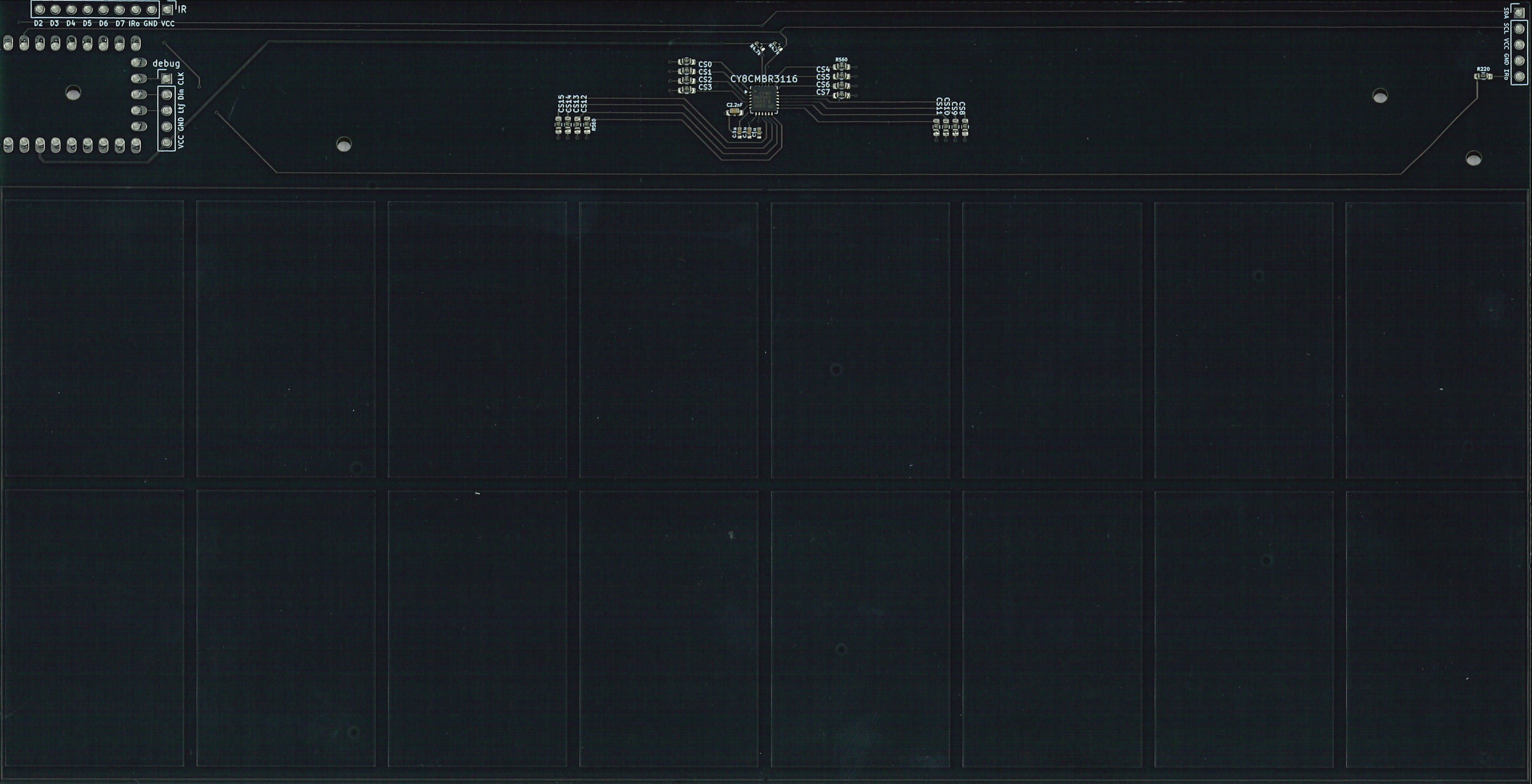
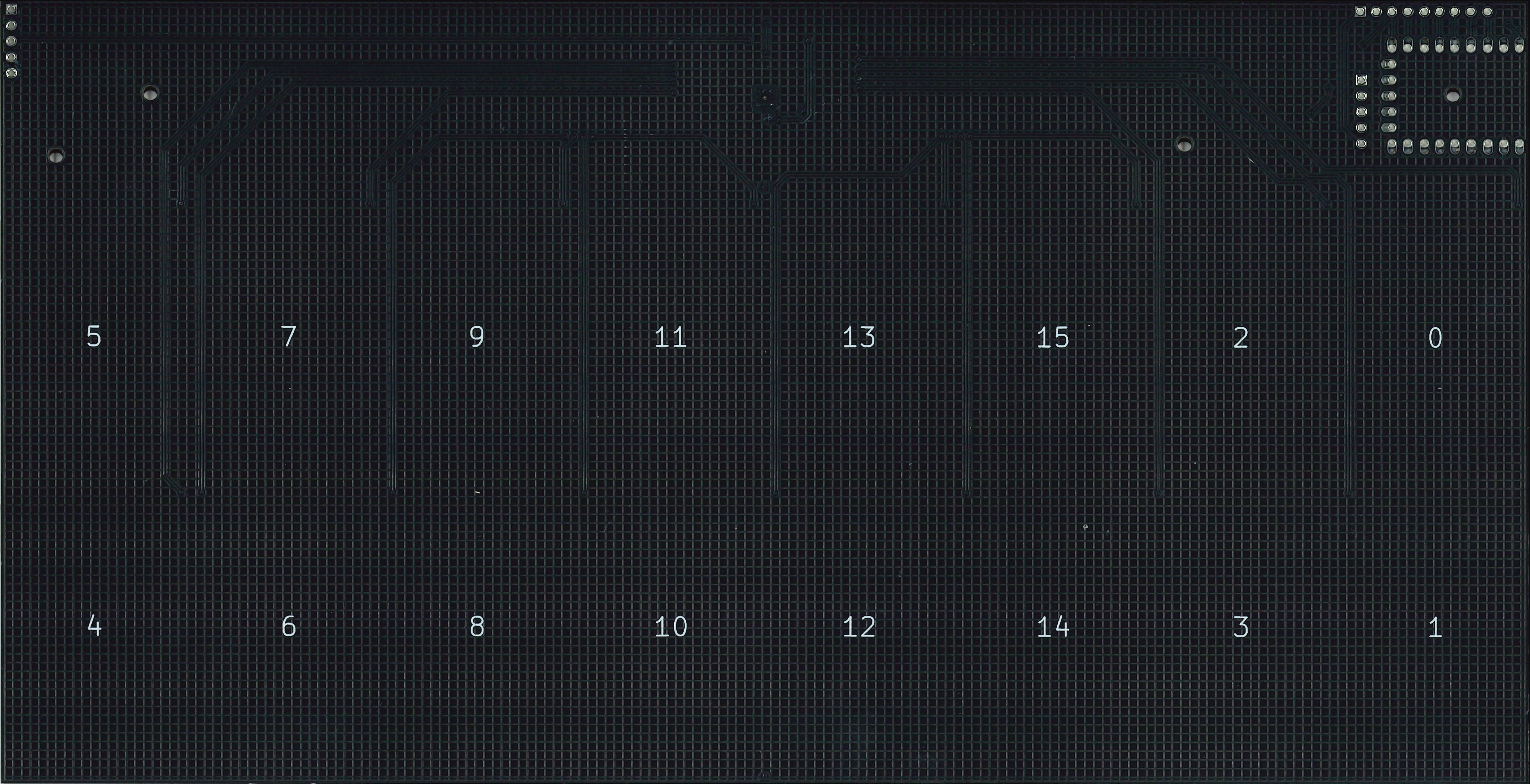
PCB × 2
IR LED × 6 ! Function haven't implented yet
IRM-3638 TSSP58038 IR reciever × 6 ! Function haven't implented yet, likely to switch to TSSP58038
RP2040-Zero × 1 (Refer as RP2040 below)
Acrylic case for touch pads (2mm thick) × 2
2mm thick acrylic × 2 + 1.6mm PCB = 5.6mm thick in total. 5.6mm + 1.6mm M2 nut + 0.5mm rubber washer = 7.7mm 5.6mm + 2.4mm M3 nut + 0.5mm rubber washer = 8.5mm
! The KiCad project is created with KiCad version 9 or 8.! Function haven't implented yet! Function haven't implented yet, likely to switch to TSSP58038! Function haven't implented yet! Function haven't implented yet, likely to switch to TSSP58038Big thank to the author(s) of these libraries
CypressCY8CMBR3116 by GitHub @sebastianregelmann The way installing the library:
Download the repo as .zip
Rename the .zip as CypressCY8CMBR3116.zip
Arduino IDE 2 > Sketch > Library > Include Library > Add .ZIP Libray...
Navigate to the .zip and select it to install the library.
!IMPORTANT! Current version of this library need to edit the .cpp file to be able to run correctly. Here's how to fix:
uint8_t CY8CMBR3116::activateSettings() { is atuint8_t error = calculateCRC();, add a line and write delay(250);.error = applyRegister(); and error = resetIC();, add a line and write delay(200);.This will increase the possibility of the setting being activated if nothing seem to go wrong.
Arduino-Pico
For developing RP2040-Zero with Arduino IDE and Arduino code.
Install the board:
Arduino IDE 2 > Arduino IDE > Preference > Additional boards manager URLs:
Add below in the end:https://github.com/earlephilhower/arduino-pico/releases/download/global/package_rp2040_index.jsonArduino IDE 2 > Boards Manager
Search "RP2040", install "Raspberry Pi Pico/RP2040/RP2350" by "Earle F. Phithower, III".Arduino IDE 2 > Tools > USB Stack > Adafruit Tiny USB to switch USB function.Full dimensions and informations (Blog, multiple pages)
Detailed dimensions and sensing method
Touch panel (ground slider) length
Sensing method (Newer information as confirmation)
Ground Pin 8 on your RP2040 to enable keyboard input.
Prepare a wooden board, print the image below that need to ensure the thickness of black line in the image are 8mm, and paste the paper with white glue.
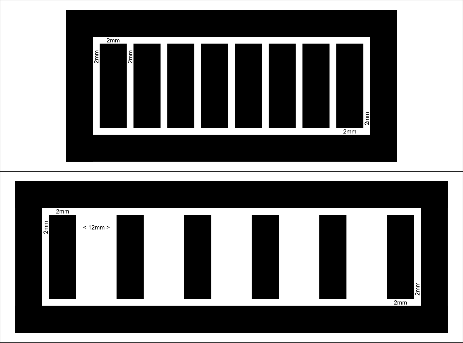
Choose one of the designs to test the result. The sticks in the middle are touch buttons, and the outter ring is ground. The 6 touch buttons one is good for playing rhythm games on PC.
After you decided the pattern you want to test, cover the black area with 8mm width copper tape and solder wires to these to pins:
Beware that the space between touch pad and ground ring is the maximum distance between your finger and the touch pad that can be detected as touched.
Only Chinese version is available at the time.

CY8C_code.ino)
HID-Project.hThis project incorporates AI-assisted development tools to optimize workflow and efficiency:
granite4:7b-a1b-h (VS Code) were used for real-time autocompletion.phi4:14b and phi4-reasoning:14b for generating initial boilerplate code and verifying logic in remote environments where hardware access was limited.All AI-generated code has been manually reviewed, refactored, and tested to ensure logic integrity and project-specific requirements.
| Qty | Value | Footprint | References |
|---|---|---|---|
| 20 | R_0402_1005Metric | Resistor_SMD:R_0402_1005Metric | 1kΩ, 1kΩ, 1kΩ, 1kΩ, 1kΩ, 1kΩ, 1kΩ, 1kΩ, 1kΩ, 1kΩ, 1kΩ, 1kΩ, 1kΩ, 1kΩ, 1kΩ, 1kΩ +4 |
| 4 | PinHeader_1x20_P2.54mm_Vertical | Connector_PinHeader_2.54mm:PinHeader_1x20_P2.54mm_Vertical | BarGraph-, BarGraph-, BarGraph+, BarGraph+ |
| 3 | C_0402_1005Metric_Pad0.74x0.62mm_HandSolder | Capacitor_SMD:C_0402_1005Metric_Pad0.74x0.62mm_HandSolder | C.1μ, C.1μ, C.1μ |
| 3 | SOIC-16_3.9x9.9mm_P1.27mm | Package_SO:SOIC-16_3.9x9.9mm_P1.27mm | 74HC595, 74HC595, 74HC595 |
| 1 | LOGO | Arnoll_Studio_Logo:Banner_Kicad | G*** |
The 31 most common of 32 parts.
It measures 57.5 × 38.2 mm and has 2 copper layers, 1.6 mm thick.
32 parts. The full list of its parts is on this page, with links to each part's symbol and footprint where PCBKit's library has them.
From the theArnoll/CHUKITHM repository on GitHub, at the commit this page was made from: the board is PCB/FormalPCB/LightIndicator.kicad_pcb and its schematic PCB/FormalPCB/FormalPCB.kicad_sch. PCBKit opens the board in the browser, with nothing to install.
Its repository states no licence, so its author keeps all rights: ask theArnoll before reusing the design.
theArnoll/CHUKITHM
A controller for an arcade game that contains ground slider and IR gesture sensor based on RP2040-Zero and CY8CMBR3116

theArnoll/CHUKITHM
A controller for an arcade game that contains ground slider and IR gesture sensor based on RP2040-Zero and CY8CMBR3116

theArnoll/CHUKITHM
A controller for an arcade game that contains ground slider and IR gesture sensor based on RP2040-Zero and CY8CMBR3116

hoglet67/RGBtoHDMI
Bare-metal Raspberry Pi project that provides pixel-perfect sampling of Retro Computer RGB/YUV video and conversion to HDMI

hackclub/OnBoard
💡 Join 1,000 teenagers and make your first PCB with a $100 grant!


octosavvi/ESPKey
Wiegand data logger, replay device and micro door-controller

zmaker/arduino_cookbook
gli sketch del nuovo progetto Arduino Cookbook e dei video di YouTube

murexrobotics/electrical
Highly integrated electronics design and printed circuit boards (PCBs) for the MATE ROV Competition. Attempt the impossible.

swharden/AVR-projects
A collection of standalone AVR projects written in C

hardenedlinux/cheap-pcb
Cheap PCB: Better understanding the current status of hardware supply chain