2 layers78.3 × 74.6 mm

 swharden/AVR-projects184
A collection of standalone AVR projects written in C
Qrss clock tx is an open-source printed circuit board by swharden, from the swharden/AVR-projects repository on GitHub, published under the MIT licence. It is a 2-layer board of 47 × 39 mm with 32 parts on 30 nets, routed with 153 tracks and 10 vias.
It is built around the ATTINY2313A-SU, 74HC04D and MMBT3904. Its parts include 12 capacitors, 7 resistors, 4 ICs, 3 diodes and 3 connectors. It belongs with the lEDs and displays boards and the AVR (ATmega, ATtiny) boards of this library.


This repository contains a growing collection of individual AVR project files for various tasks. I personally use these projects as starting points for new microcontroller projects, or reference for common procedudures I would otherwise have to go back to the datasheet for (timers, counters, frequency counting or synthesis, interrupts, UART, I2C, ADC, etc). Each folder is self-contained and has batch scripts to set fuses to change the clock source (internal RC oscillator at 8MHz, div/8 for 1MHz, or external crystal typically up to 20 MHz)
These are some of my favorites:
I almost always use AVRISPmkII and AVRdude (launched from a batch script) to program my chips. I virtually never use AVRStudio. I typically develop in a Windows environment, but the code (and AVRdude) works the same in Linux.
| Note | Picture |
|---|---|
| AVRISPmkII is a ceap, fast, and convenient AVR programmer. | 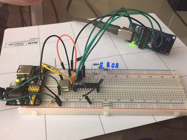 |
| Bus Pirate technically can program AVRs, but it's so slow it's not practical. Here's a post I wrote about it. I like the bus pirate when I need to use software to measure voltages and toggle pins. It's slow though, because the handshake it bit-banged and it takes tens of seconds to program an AVR. For just programming, I prefer an (ebay knockoff) AVR ISP mkII. Definately check out AVRDudess as a GUI for AVRDude. I usually get a standard command for a project and put it in a batch file in the same folder. |  |
| AVRDudess can simplify programming of code and fuses. | 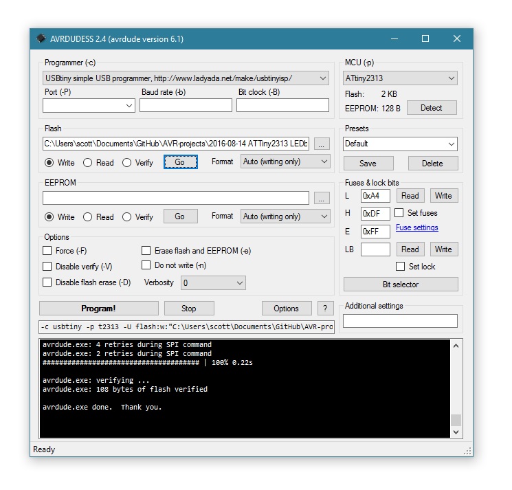 |
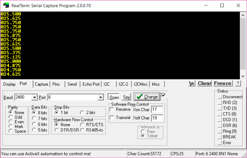
I highly recommend RealTerm for Windows
| chip | pinout | datasheets |
|---|---|---|
| ATMega328 | 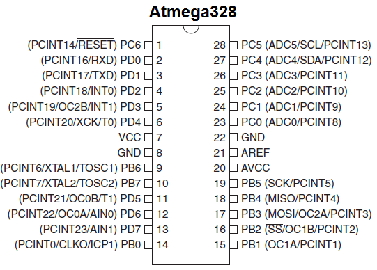 | [summary] [complete] |
| ATTiny2313 | 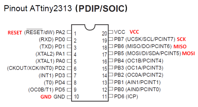 | [summary] [complete] |
| ATTiny45 | 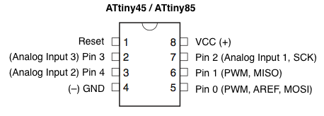 | [summary] [complete] |
if(PIND&(1<<PD7)){doSomething();} // runs doSomething() if PD7 is HIGHPORTD|=(1<<PD6); // sets PD6 high
PORTD&=~(1<<PD6); // sets PD6 low
PORTD^=(1<<PD6); // flips the state of PD6#include <util/delay.h>
void waitMs1(){_delay_ms(1);}
void waitMs(int ms){while (ms-->0){waitMs1();}}
void waitSec(int sec){while (sec-->0){waitMs(1000);}}| Qty | Value | Footprint | References |
|---|---|---|---|
| 6 | .1u | Capacitor_SMD:C_0805_2012Metric_Pad1.15x1.40mm_HandSolder | C1, C3, C4, C6, C7, C8 |
| 4 | 1K | Resistor_SMD:R_0805_2012Metric_Pad1.15x1.40mm_HandSolder | R1, R2, R3, R6 |
| 2 | 100K | Resistor_SMD:R_0805_2012Metric_Pad1.15x1.40mm_HandSolder | R4, R7 |
| 2 | 100p | Capacitor_SMD:C_0805_2012Metric_Pad1.15x1.40mm_HandSolder | C2, C5 |
| 2 | 10p | Capacitor_SMD:C_0805_2012Metric_Pad1.15x1.40mm_HandSolder | C9, C11 |
| 2 | 30p | Capacitor_SMD:C_0805_2012Metric_Pad1.15x1.40mm_HandSolder | C10, C12 |
| 2 | LM78M05_TO252 | Package_TO_SOT_SMD:TO-252-2 | U1, U2 |
| 1 | 10.14MHz | Crystal:Crystal_HC49-4H_Vertical | Y1 |
| 1 | 10K | Resistor_SMD:R_0805_2012Metric_Pad1.15x1.40mm_HandSolder | R5 |
| 1 | 74HC04 | Package_SO:SOIC-14_3.9x8.7mm_P1.27mm | U3 |
| 1 | ATtiny2313A-SU | Package_SO:SOIC-20W_7.5x12.8mm_P1.27mm | U4 |
| 1 | Conn_Coaxial | Connector_Coaxial:SMA_Amphenol_132134-11_Vertical | J3 |
| 1 | Ferrite_Bead | Resistor_SMD:R_0805_2012Metric_Pad1.15x1.40mm_HandSolder | FB1 |
| 1 | ICSP | Connector_PinHeader_2.54mm:PinHeader_1x05_P2.54mm_Vertical | J2 |
| 1 | MMBT3904 | Package_TO_SOT_SMD:SOT-23 | Q1 |
| 1 | POWER | LED_SMD:LED_0805_2012Metric_Pad1.15x1.40mm_HandSolder | D1 |
| 1 | PWR | Connector_PinHeader_2.54mm:PinHeader_1x02_P2.54mm_Vertical | J1 |
| 1 | STAT | LED_SMD:LED_0805_2012Metric_Pad1.15x1.40mm_HandSolder | D4 |
| 1 | VAR2 | Diode_SMD:D_0805_2012Metric_Pad1.15x1.40mm_HandSolder | D3 |
It measures 47 × 39 mm and has 2 copper layers, 1.6 mm thick.
32 parts, built around the ATTINY2313A-SU, 74HC04D and MMBT3904. The full list of its parts is on this page, with links to each part's symbol and footprint where PCBKit's library has them.
From the swharden/AVR-projects repository on GitHub, at the commit this page was made from: the board is QRSS TX - clock tx/PCB/qrss-clock-tx.kicad_pcb. PCBKit opens the board in the browser, with nothing to install.
Its repository publishes it under the MIT licence: you may reuse it on that licence's terms (keep the author's notice, and for a copyleft licence share your changes alike).


bga/avr-hid-usb-init-tester
Avr attiny2313 soft usb hid "keyboard" for testing bios usb initialization. Device is blinking if bios assign usb endpoint address and continue sending USB SOF (ie bios in alive).


lyase/hello-bulb
making the simplest usb device using atmel2313 the board design is available in kicad format .code is c, licence GPL V3


13chuck13-ua/Tiny-Sound-Source
AVR ATtny as LPT DAC compatible with Covox Speech Thing and Disney Sound Source.