
2 layers50 × 50 mm

 theapi/denbit2
Training wheels for the nodemcu
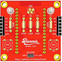
Nrf nano is an open-source printed circuit board by theapi, from the theapi/denbit repository on GitHub, published under the MIT licence. It is a 2-layer board of 50 × 50 mm with 21 parts on 35 nets.
It is built around the NRF24L01. Its parts include 11 connectors, 5 resistors, 3 diodes and 2 switches.
##Installation
Download and install the Aduino IDE plus any drivers it asks too.
You can use the free version with the JUST DOWNLOAD link. No need to donate money.
Install the NodeMCU "board" into the Arduino IDE:
Start Arduino and open Preferences window.
Enter http://arduino.esp8266.com/stable/package_esp8266com_index.json into Additional Board Manager URLs field and click Ok:

Tools > Board > Boards Manager...:
esp8266 by ESP8266 Community, click More info and select version 2.2.0 then click install:
Click Close once it installed
Select the NodeMCU 1.0 board from Tools > Board menu and select NodeMCU 1.0 (ESP-12E Module):

Install the denbit library
Sketch -> Include Library -> Add .ZIP Library... then select the file downloaded in the step above.
Rename ~/Documents/Arduino/libraries/denbit/src/default_config.h to config.h and edit its content to have the wifi access details and your denbit's name.
Mac users, if programming with a usb cable, install the driver from www.silabs.com (direct link).
Port the usb is connected to/dev/cu.SLAB_USBtoUARTCOMM and a number so something like COMM4File -> Examples -> Denbit -> Basics -> Blink


delay(1000) is delay(500), then compile & upload again. The green LED will now blink twice as fast| Qty | Value | Footprint | References |
|---|---|---|---|
| 4 | 100R | Resistors_ThroughHole:Resistor_Horizontal_RM10mm | R2, R3, R4, R5 |
| 4 | MOUNT_HOLE | Mounting_Holes:MountingHole_3.2mm_M3_Pad | P8, P9, P10, P11 |
| 2 | CONN_01X06 | Socket_Strips:Socket_Strip_Straight_1x06 | P5, P7 |
| 2 | CONN_01X15 | Socket_Strips:Socket_Strip_Straight_1x15 | P4, P6 |
| 2 | LED | LEDs:LED-5MM | D1, D2 |
| 2 | SW_PUSH | Buttons_Switches_ThroughHole:SW_PUSH_SMALL | SW1, SW2 |
| 1 | 180R | Resistors_ThroughHole:Resistor_Horizontal_RM10mm | R1 |
| 1 | 5V_OUT | Socket_Strips:Socket_Strip_Straight_1x02 | P1 |
| 1 | ALT_PWR | Pin_Headers:Pin_Header_Straight_1x02 | P2 |
| 1 | LED_RCBG | LEDs:LED-RGB-5MM_Common_Cathode | D3 |
| 1 | NRF_24L01 | NRF_24L01 | P3 |
It measures 50 × 50 mm and has 2 copper layers, 1.6 mm thick.
21 parts, built around the NRF24L01. The full list of its parts is on this page, with links to each part's symbol and footprint where PCBKit's library has them.
From the theapi/denbit repository on GitHub, at the commit this page was made from: the board is kicad/nrf_nano/nrf_nano.kicad_pcb. PCBKit opens the board in the browser, with nothing to install.
Its repository publishes it under the MIT licence: you may reuse it on that licence's terms (keep the author's notice, and for a copyleft licence share your changes alike).

NikodemBartnik/Mini-Mars-Rover
Educational robotic platform made to look like a mini mars rover

DAlexis/caustic-lasertag-system
Caustic project is a full-featured indoor and outdoor lasertag system

CGrassin/biosignals
Board for the acquisition of bio-potentials (EMG, ECG, EEG, etc.).

microdynamics-robot-quadcopter/breeze_electronics_design
This project is created and managed by EDA softwares, which contains the breeze quadcopter's component library, footprint library, schematic, printed circuit boards, etc.


