
2 layers143.3 × 116.6 mm

Reverse engineering of a truck steering-wheel cruise/retarder switch panel (SKNY_FXP1 V1.1): schematic, netlist, resistor ladder decode, Arduino + Python toolchain
UIbuttons is an open-source printed circuit board by ThatguyCplus, from the ThatguyCplus/truck-switch-reverse-eng repository on GitHub, published under the MIT licence. It is a 2-layer board of 92.4 × 33.8 mm with 63 parts on 28 nets, routed with 277 tracks and 20 vias.
Its parts include 26 resistors, 10 diodes and 1 connector.
Complete reverse engineering of a truck steering-wheel cruise/retarder switch panel: schematic, netlist, resistor values, connector pinout, and an Arduino + Python toolchain that reads all twelve buttons.
The board identifies itself on the silkscreen as SKNY_FXP1 V1.1 / 20220615 / G295197.
It is sold as a replacement cruise-control switch module for Scania L/P/G/R/S-series
tractors (OEM reference 2545507).
Independent research. Not affiliated with, authorised by, or endorsed by Scania or any vehicle manufacturer. Manufacturer and part numbers appear solely to identify which part was studied. Everything here was derived by measuring a unit purchased on the open market — no manufacturer documentation, firmware, or software was used or reproduced. The panel is entirely passive: resistors, LEDs, and switch contacts, with no firmware, encryption, or access control of any kind.
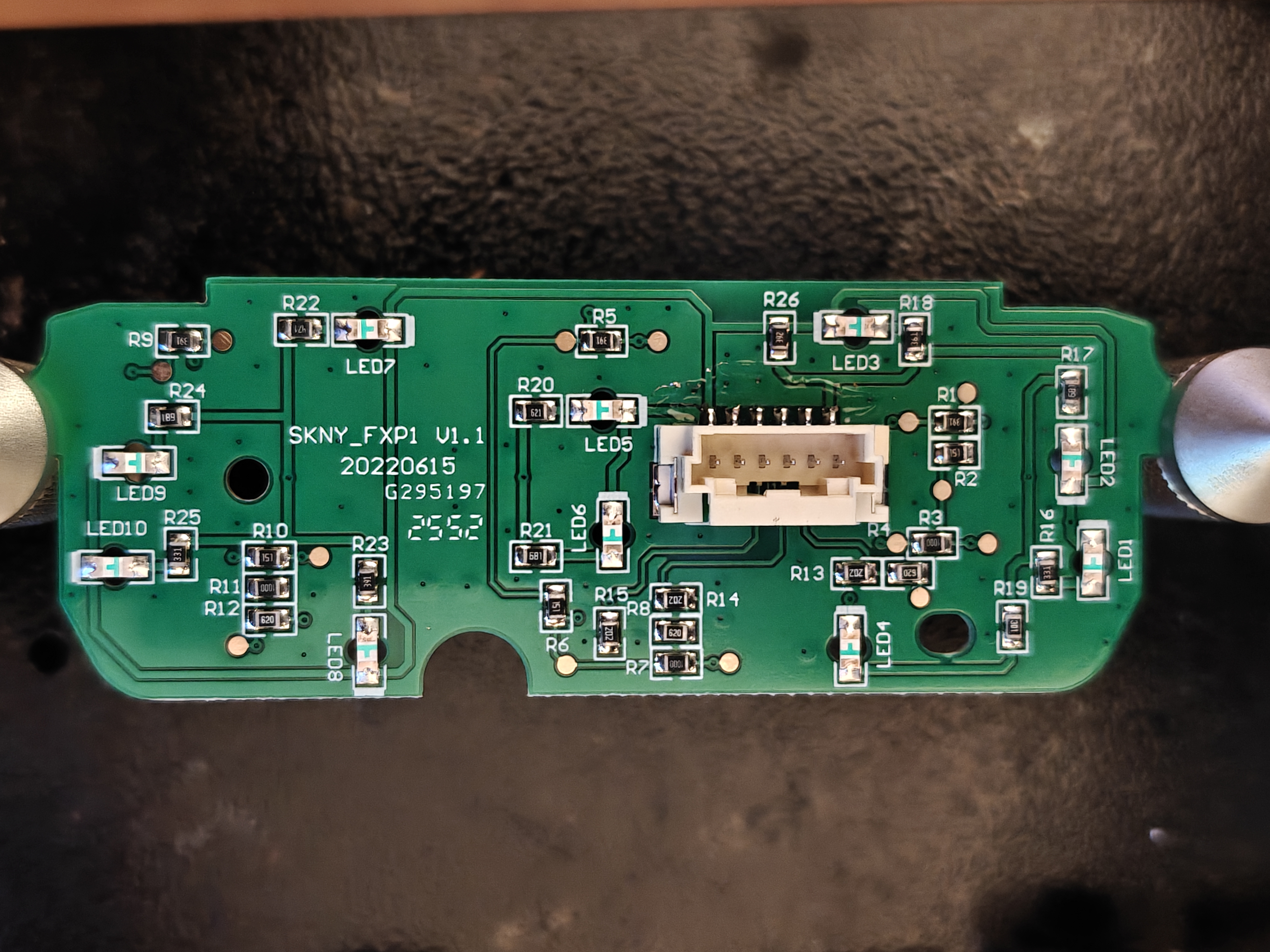
A 12-button steering-wheel panel with white LED backlighting, connected to the truck by a single 6-pin cable. Twelve buttons on three wires is achieved with three analog resistor ladders — a very common automotive pattern, because it gets the wire count down and gives open/short fault detection for free.
| Buttons | 12 (in five physical zones) |
| Backlight | 10× white LED, individually ballasted |
| Connector | Molex DuraClik, 6-pin (560020-0620 footprint) |
| Signal wires | 3 analog ladder lines |
| Active components | none — fully passive |
| Pin | Function | Notes |
|---|---|---|
| 1 | Backlight + | ~5 V dimmable illumination rail |
| 2 | Ladder A | cruise speed rocker (two-stage) |
| 3 | Ladder B | cruise resume/cancel + follow distance |
| 4 | Ladder C | downhill/retarder |
| 5 | Ground | |
| 6 | Backlight − | LED cathode common |
Each signal line is an identical series ladder — 62 → 100 → 150 → 390 Ω — with a 2 kΩ pulldown to ground. Every button shorts its own tap to ground, so each button presents a distinct resistance at the connector pin.
J1 pin ──62Ω──┬──100Ω──┬──150Ω──┬──390Ω──┬
              │        │        │        │
             SW1      SW2      SW3      SW4          2kΩ pulldown
              │        │        │        │            to GND
             GND      GND      GND      GND
The 2 kΩ pulldown is what makes the scheme fault-tolerant: an unplugged connector or a broken wire reads open-circuit, and a shorted harness reads ~0 Ω. Both are distinguishable from every legitimate button state.
Resistance seen at the pin, and the resulting 10-bit ADC value with a 1 kΩ pull-up to 5 V (the wiring used by the tools in this repo):
| Tap | Ladder | ∥ 2 kΩ | ADC | Line A (pin 2) | Line B (pin 3) | Line C (pin 4) |
|---|---|---|---|---|---|---|
| 1 | 62 Ω | 60 Ω | 58 | Cruise − BIG | Cruise CANCEL | Downhill CANCEL |
| 2 | 162 Ω | 150 Ω | 133 | Cruise − SMALL | Follow dist + | Downhill − |
| 3 | 312 Ω | 270 Ω | 217 | Cruise + BIG | Cruise RESUME | Downhill RESUME |
| 4 | 702 Ω | 520 Ω | 350 | Cruise + SMALL | Follow dist − | Downhill + |
| — | idle | 2 kΩ | 682 | — | — | — |
| — | open | ∞ | 1023 | fault | fault | fault |
Five zones, left to right, twelve contacts total:
| Zone | Buttons | Line |
|---|---|---|
| Cruise resume / cancel | 2 | B (taps 3, 1) |
| Cruise speed rocker | 4 — two-stage: light press = small step, firm = big step | A (all four) |
| Follow distance | 2 | B (taps 2, 4) |
| Downhill rocker | 2 | C (taps 2, 4) |
| Retarder resume / cancel | 2 | C (taps 3, 1) |
The cruise rocker is the only two-stage control, which is why one whole ladder is spent on a single rocker.
Within a line the taps are a series chain, so grounding one tap shorts out every tap beyond it. Holding two buttons on the same line produces a reading that is bit-for-bit identical to holding the nearer-to-connector one alone — there is no signal to recover.
Rule: the reported button is the lowest-index one held; everything past it is invisible.
Enumerating all 2¹² combinations (tools/enumerate_combos.py →
docs/button_combinations.csv):
total combinations      : 4096
fully observable        : 125
at least one masked     : 3971
distinct ADC signatures : 125   (5 states ^ 3 lines)
The three ladders are independent, so up to 3 buttons — one per line — register simultaneously. That is the hard ceiling of the design, not a software limit.
Ten white LEDs sit in parallel between pin 1 and pin 6, each with its own ballast resistor. The values are deliberately unequal — that is brightness balancing, so legends behind heavier diffusers get more current and the panel looks even.
| LED | Ballast | Value | LED | Ballast | Value | |
|---|---|---|---|---|---|---|
| LED1 | R16 | 330 Ω | LED6 | R21 | 680 Ω | |
| LED2 | R17 | 680 Ω | LED7 | R22 | 470 Ω | |
| LED3 | R18 | 360 Ω | LED8 | R23 | 390 Ω | |
| LED4 | R19 | 300 Ω | LED9 | R24 | 680 Ω | |
| LED5 | R20 | 620 Ω | LED10 | R25 | 330 Ω |
R26 (3.9 kΩ) bridges the rail with no LED — a bleeder that keeps the dimmer's off-state leakage from ghost-lighting the panel.
The LEDs are a 5 mA white part (2.9 V forward drop typical). Working backwards from the ballast values, the illumination rail is ~5 V, not 24 V — at 12 V the 330 Ω legs would pull 27 mA and at 24 V over 60 mA, well beyond the die rating. Total panel draw is about 47 mA including R26. The truck regulates and PWM-dims this rail before it reaches the wheel.
| Ref | Code | Value | Role | Ref | Code | Value | Role | |
|---|---|---|---|---|---|---|---|---|
| R1 | 391 | 390 Ω | ladder A tap 4 | R14 | 202 | 2 kΩ | pulldown B | |
| R2 | 151 | 150 Ω | ladder A tap 3 | R15 | 202 | 2 kΩ | pulldown C | |
| R3 | 1000 | 100 Ω | ladder A tap 2 | R16 | 331 | 330 Ω | LED1 | |
| R4 | 620 | 62 Ω | ladder A tap 1 | R17 | 681 | 680 Ω | LED2 | |
| R5 | 391 | 390 Ω | ladder B tap 4 | R18 | 361 | 360 Ω | LED3 | |
| R6 | 151 | 150 Ω | ladder B tap 3 | R19 | 301 | 300 Ω | LED4 | |
| R7 | 1000 | 100 Ω | ladder B tap 2 | R20 | 621 | 620 Ω | LED5 | |
| R8 | 620 | 62 Ω | ladder B tap 1 | R21 | 681 | 680 Ω | LED6 | |
| R9 | 391 | 390 Ω | ladder C tap 4 | R22 | 471 | 470 Ω | LED7 | |
| R10 | 151 | 150 Ω | ladder C tap 3 | R23 | 391 | 390 Ω | LED8 | |
| R11 | 1000 | 100 Ω | ladder C tap 2 | R24 | 681 | 680 Ω | LED9 | |
| R12 | 620 | 62 Ω | ladder C tap 1 | R25 | 331 | 330 Ω | LED10 | |
| R13 | 202 | 2 kΩ | pulldown A | R26 | 392 | 3.9 kΩ | rail bleeder |
Note that many chips are mounted rotated 180°, so their codes read upside-down in
photographs — 189 on the board is a 681. Several values were only settled by
rotating the image until neighbouring silkscreen read the right way up.
Every ladder node is brought out to a test pad, which makes fault-finding easy:
| Node | Line A | Line B | Line C |
|---|---|---|---|
| tap 1 | TP1, TP2 | TP8 | TP13 |
| tap 2 | TP3, TP6 | TP9 | TP12 |
| tap 3 | TP5 | TP7 | TP14 |
| tap 4 | TP4 | TP10 | TP11 |
Six wires and three resistors:
| J1 pin | Arduino |
|---|---|
| 1 | 5 V |
| 2 | A0, plus 1 kΩ from A0 to 5 V |
| 3 | A1, plus 1 kΩ from A1 to 5 V |
| 4 | A2, plus 1 kΩ from A2 to 5 V |
| 5 | GND |
| 6 | GND, or a low-side MOSFET on D9 for PWM dimming |
Do not use the internal pull-ups. At ~35 kΩ they would squash every button below 0.1 V and make the four taps indistinguishable. The external 1 kΩ spreads the five states across the ADC range with 75–330 counts between them — far more margin than the ADC's noise floor.
Worst-case current is 4.7 mA per line, and the source impedance the ADC sees never exceeds ~1 kΩ, comfortably inside the ATmega328P's 10 kΩ recommendation.
Flash firmware/panel_reader/panel_reader.ino.
It streams raw averaged ADC counts as a,b,c at ~60 Hz and deliberately does not
decode on-device, so thresholds can be retuned on the host without reflashing.
pip install pyserial
python tools/panel_gui.py      # live monitor
python tools/panel_diag.py     # ladder fault finder
On Windows, tools/install_shortcuts.ps1 creates desktop shortcuts, or use the
.bat launchers (which check for pyserial first).
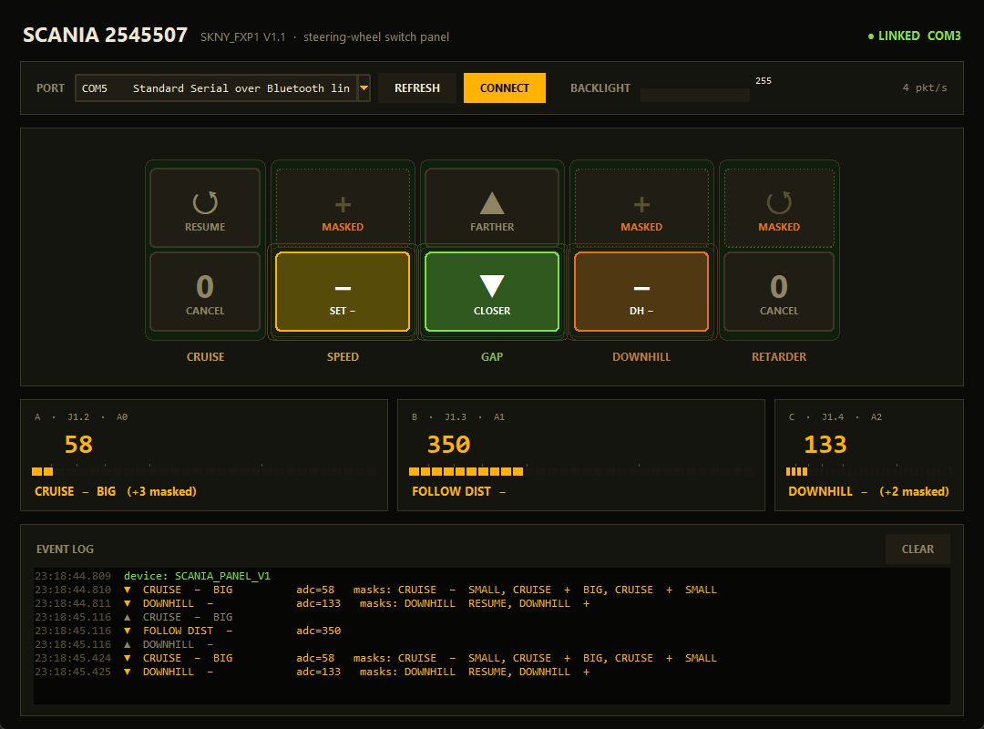
Panel monitor — lights up a drawing of the real panel as buttons are pressed. Buttons that are held but electrically masked are labelled as such rather than silently ignored.
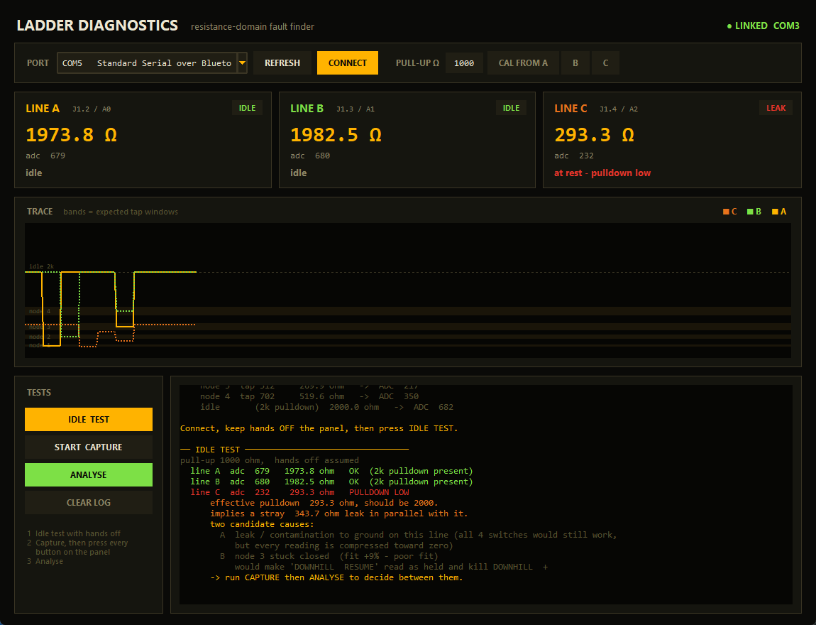
Ladder diagnostics — works in the resistance domain rather than raw ADC, converting each reading back to ohms so a fault maps onto a physical node. It fits two competing models (a stuck switch on a healthy 2 kΩ line, versus a leak dragging the pulldown down) and reports which one the data actually supports.
https://github.com/user-attachments/assets/56d19fef-1fe3-4a56-b6b1-583ad4992691
hardware/    KiCad 10 project — schematic, PCB, exported netlist
photos/      board photographs, plus PDFs with the traces drawn over
firmware/    Arduino sketch
tools/       Python monitor, diagnostics, combination enumerator
docs/        full combination table, screenshots
The .kicad_pcb is large (~31 MB) because it embeds the board photographs that were
used as tracing underlays while the copper was being followed.
photos/ — one per side, with the component-side image mirrored so pad positions
line up between the two.The netlist was the useful cross-check throughout — the three ladders coming out identical (62/100/150/390 + 2 kΩ) was strong evidence the trace-following was right, and it caught two transcription errors that the photographs alone had not.
Code and documentation: MIT.
The measured electrical characteristics are facts about a physical object and are not claimed as anyone's intellectual property. Photographs are original work by the repository author.
| Qty | Value | Footprint | References |
|---|---|---|---|
| 14 | TestPoint | TestPoint:TestPoint_Pad_D1.5mm | TP1, TP2, TP3, TP4, TP5, TP6, TP7, TP8, TP9, TP10, TP11, TP12, TP13, TP14 |
| 12 | Push_Button | PCM_SparkFun-Switch:Push_SMD_6x3.5mm | +Downhill1, BigCruise-1, BigCruise+1, CancelCruiseControl1, CancelDownhillControl1, DecreaseFollowDistance1, DownHill-1, IncreaseFollowDistance1, ResumeCruiseControl1, ResumeDownHillControl1, SmallCruise-1, SmallCruise+1 |
| 10 | LED_1206_White | PCM_LED_SMD_AKL:LED_1206_3216Metric | LED1, LED2, LED3, LED4, LED5, LED6, LED7, LED8, LED9, LED10 |
| 4 | 391 | PCM_Resistor_SMD_AKL:R_0805_2012Metric | R1, R5, R9, R23 |
| 3 | 1000 | PCM_Resistor_SMD_AKL:R_0805_2012Metric | R3, R7, R11 |
| 3 | 151 | PCM_Resistor_SMD_AKL:R_0805_2012Metric | R2, R6, R10 |
| 3 | 202 | PCM_Resistor_SMD_AKL:R_0805_2012Metric | R13, R14, R15 |
| 3 | 620 | PCM_Resistor_SMD_AKL:R_0805_2012Metric | R4, R8, R12 |
| 3 | 681 | PCM_Resistor_SMD_AKL:R_0805_2012Metric | R17, R21, R24 |
| 2 | 331 | PCM_Resistor_SMD_AKL:R_0805_2012Metric | R16, R25 |
| 1 | 301 | PCM_Resistor_SMD_AKL:R_0805_2012Metric | R19 |
| 1 | 361 | PCM_Resistor_SMD_AKL:R_0805_2012Metric | R18 |
| 1 | 392 | PCM_Resistor_SMD_AKL:R_0805_2012Metric | R26 |
| 1 | 471 | PCM_Resistor_SMD_AKL:R_0805_2012Metric | R22 |
| 1 | 5600200620 | molex:CONN_SD-560020-001_06_MOL | J1 |
| 1 | 621 | PCM_Resistor_SMD_AKL:R_0805_2012Metric | R20 |
It measures 92.4 × 33.8 mm and has 2 copper layers, 1.6 mm thick.
63 parts. The full list of its parts is on this page, with links to each part's symbol and footprint where PCBKit's library has them.
From the ThatguyCplus/truck-switch-reverse-eng repository on GitHub, at the commit this page was made from: the board is hardware/UIbuttons.kicad_pcb and its schematic hardware/UIbuttons.kicad_sch. PCBKit opens the board in the browser, with nothing to install.
Its repository publishes it under the MIT licence: you may reuse it on that licence's terms (keep the author's notice, and for a copyleft licence share your changes alike).


coseyfannitutti/discipad
17-key numpad assembled with only through hole components, including usb type-c

eddyem/stm32samples
Code samples and ready projects based on bare-metal STM32

pekkaroi/bldc-drive
Cheap and simple brushless DC motor driver designed for CNC applications using STM32 microcontroller


mzuelch/CATs-Eurosynth
Analog Synth Eurorack Modules