
2 layers62 × 42 mm

 Green-bms/SmartBMS756
Open source Smart Battery Management System
Interface board 1 is an open-source printed circuit board by Green-bms, from the Green-bms/SmartBMS repository on GitHub. It is a 2-layer board of 107 × 54 mm with 63 parts on 112 nets, routed with 598 tracks and 50 vias.
It is built around the NE555D, ULN2003A and PMBT2222. Its parts include 18 connectors, 15 resistors, 10 diodes, 9 switches and 6 capacitors. It belongs with the power and interfaces and adapters boards of this library.


Open source Smart Battery Management System
Youtube presentation: https://youtu.be/0XNe25lMs6U?si=eK-90N3kao_sy4zy
Official page: https://hackaday.io/project/181453-green-bms
Smart BMS is an Open Source Battery Management System for Lithium Cells (Lifepo4, Li-ion, NCM, etc.) Battery Pack.
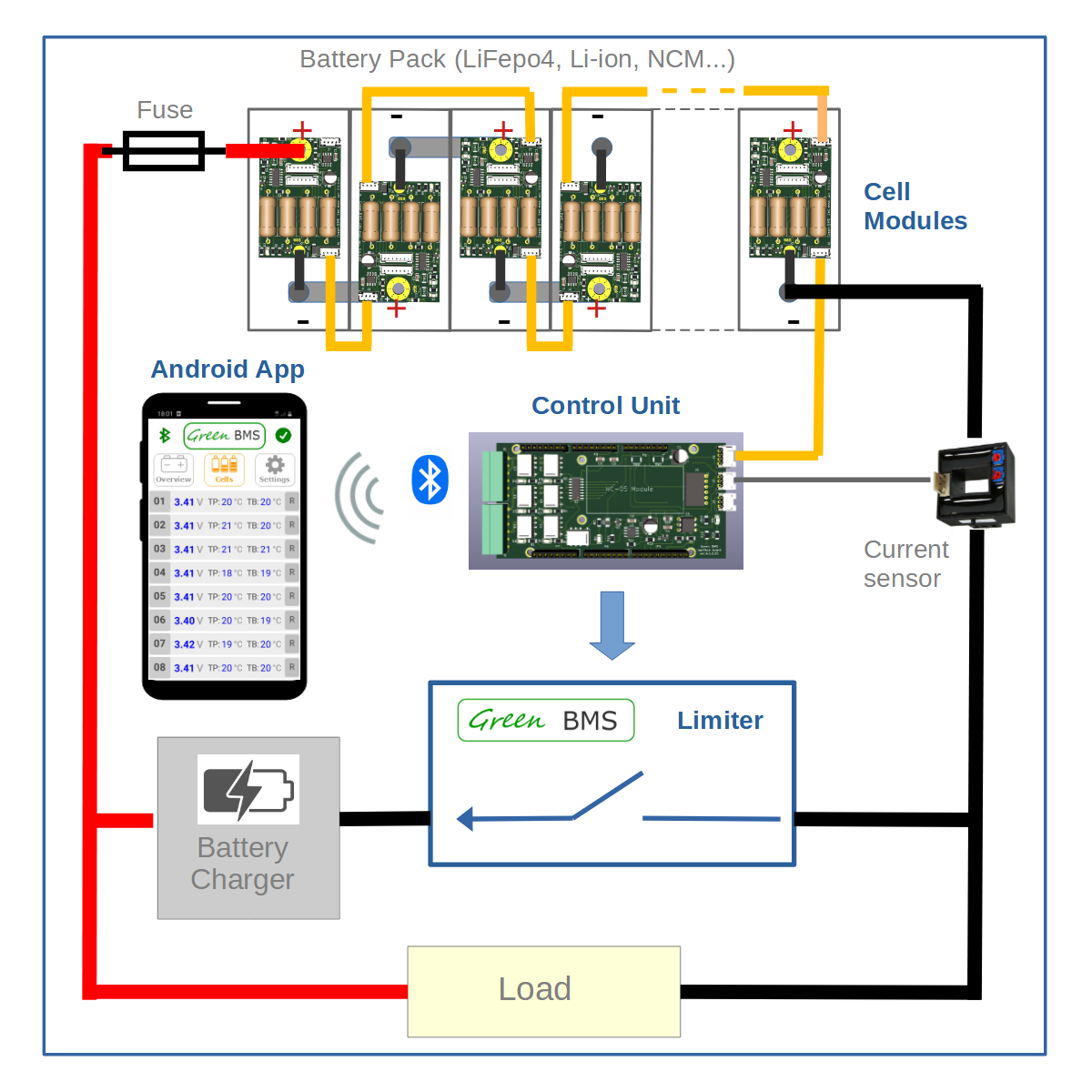
The main functions of BMS are:
Smart BMS consists of four main components:
The voltage and the temperature values of each cell are acquired by the relevant Cell Module (based on Attiny microcontroller) and sent to Control Unit (based on Arduino Mega microcontroller) through a serial I2C line.
Control Unit starts or stop charging (by output relay) through Limiter, that includes a power relay for opening or closing the charging circuit.
Control Unit can also start or stop discharging by output relay.
When during charging a cell reaches the “Balance voltage value parameter”, the Cell Module connects the balance resistors in order to perform the cell bleeding.
When just one cell of the pack is balancing, Control Unit activates the current limit function inside the Limiter (the charging current is limited to 1A).
Control Unit can be connected with a Smartphone (or a Tablet) by Bluetooth.
By “Green BMS” Android app (available on Play Store) it is possible to check the Battery Pack status (total voltage, current load, state of charge…) , to check the actual voltage and temperature values of each cell and to perform several settings.
The Green BMS Android app is available here: Green-BMS App
Step by step instructions for make Green BMS are available here: https://hackaday.io/project/181453/instructions
https://www.youtube.com/channel/UCdJnQnmzJSQNOAGbZR5iExA
Subscribe please... :smile:
The project was created using the following Open source applications:
Lithium and other batteries are dangerous and must be treated with care.
Lithium and other batteries are potentially hazardous and can present a serious fire hazard if damaged, defective or improperly used.
Green BMS is a "do it yourself" project, with no warranties whatsoever.
Green BMS assumes no responsibility for any errors or inaccuracies that may appear in any documentation or file or any software that may be provided.
The use of this project is done entirely at your own risk and responsibility.
The use of this project may not be compliant with local laws or regulations.
Green BMS has been certified as open source hardware by the Open Source Hardware Association, with the UID: IT000007.
Certificate link: (https://certification.oshwa.org/it000007.html)
This work is licensed under a Creative Commons Attribution-ShareAlike 4.0 International License. https://creativecommons.org/licenses/by-sa/4.0/
Share — copy and redistribute the material in any medium or format
Adapt — remix, transform, and build upon the material for any purpose, even commercially. This license is acceptable for Free Cultural Works. The licensor cannot revoke these freedoms as long as you follow the license terms.
Attribution — You must give appropriate credit, provide a link to the license, and indicate if changes were made. You may do so in any reasonable manner, but not in any way that suggests the licensor endorses you or your use.
ShareAlike — If you remix, transform, or build upon the material, you must distribute your contributions under the same license as the original.
No additional restrictions — You may not apply legal terms or technological measures that legally restrict others from doing anything the license permits.
You do not have to comply with the license for elements of the material in the public domain or where your use is permitted by an applicable exception or limitation. No warranties are given. The license may not give you all of the permissions necessary for your intended use. For example, other rights such as publicity, privacy, or moral rights may limit how you use the material.
| Qty | Value | Footprint | References |
|---|---|---|---|
| 9 | 1K | Resistor_SMD:R_1206_3216Metric | R0, R1, R2, R3, R4, R5, R6, R8, R10 |
| 8 | LED | LED_SMD:LED_1206_3216Metric | D0, D1, D2, D3, D4, D5, D6, D9 |
| 7 | G6K-2 | Relay_SMD:Relay_DPDT_Omron_G6K-2F-Y | K0, K1, K2, K3, K4, K5, K6 |
| 6 | CONN_01X01 | Socket_Arduino_Mega:Arduino_1pin | P8, P9, P10, P11, P12, P13 |
| 4 | 100n | Capacitor_SMD:C_1206_3216Metric | C2, C3, C4, C6 |
| 2 | 100/16v | Capacitor_SMD:CP_Elec_6.3x5.8 | C1, C5 |
| 2 | Analog | Socket_Arduino_Mega:Socket_Strip_Arduino_1x08 | P3, P4 |
| 2 | Conn_01x03 | Connector_JST:JST_PH_S3B-PH-K_1x03_P2.00mm_Horizontal | J2, J3 |
| 2 | Conn_01x06 | Connector_Phoenix_MC:PhoenixContact_MC_1,5_6-G-3.5_1x06_P3.50mm_Horizontal | J5, J6 |
| 2 | D | Diode_SMD:D_1206_3216Metric | D8, D10 |
| 2 | PMBT2222 | Package_TO_SOT_SMD:SOT-23 | Q1, Q2 |
| 2 | SW_Push | Button_Switch_SMD:SW_Push_SPST_NO_Alps_SKRK | SW1, SW2 |
| 1 | 10 | Resistor_SMD:R_1206_3216Metric | R12 |
| 1 | 270 | Resistor_SMD:R_1206_3216Metric | R13 |
| 1 | 2K | Resistor_SMD:R_1206_3216Metric | R9 |
| 1 | 330 | Resistor_SMD:R_1206_3216Metric | R15 |
| 1 | 470 | Resistor_SMD:R_1206_3216Metric | R14 |
| 1 | 47k | Resistor_SMD:R_1206_3216Metric | R11 |
| 1 | 4N35 | Package_DIP:DIP-6_W7.62mm | U1 |
| 1 | Communication | Socket_Arduino_Mega:Socket_Strip_Arduino_1x08 | P7 |
| 1 | Conn_01x04 | Connector_JST:JST_PH_S4B-PH-K_1x04_P2.00mm_Horizontal | J1 |
| 1 | Conn_01x06 | Connector_PinSocket_2.54mm:PinSocket_1x06_P2.54mm_Horizontal | J4 |
| 1 | NE555D | Package_SO:SOIC-8_3.9x4.9mm_P1.27mm | U2 |
| 1 | PWM | Socket_Arduino_Mega:Socket_Strip_Arduino_1x10 | P5 |
| 1 | PWM | Socket_Arduino_Mega:Socket_Strip_Arduino_1x08 | P6 |
| 1 | Power | Socket_Arduino_Mega:Socket_Strip_Arduino_1x08 | P2 |
| 1 | ULN2003A | Package_SO:SOIC-16_3.9x9.9mm_P1.27mm | U3 |
It measures 107 × 54 mm and has 2 copper layers, 1.6 mm thick.
63 parts, built around the NE555D, ULN2003A and PMBT2222. The full list of its parts is on this page, with links to each part's symbol and footprint where PCBKit's library has them.
From the Green-bms/SmartBMS repository on GitHub, at the commit this page was made from: the board is 04_Interface board/Hardware/Kikad_Interface_board_1/Interface_board_1.kicad_pcb. PCBKit opens the board in the browser, with nothing to install.
Its repository states no licence, so its author keeps all rights: ask Green-bms before reusing the design.


dbalsom/arduinoX86
An interface between an Arduino Due or Arduino GIGA and 8088, 8086, V20, V30, 186 or 286 CPUs

fehlfarbe/arduino-motorfocus
Arduino motorfocus with moonlite protocol for telescopes

Scottapotamas/zaphod-bot
A DIY high performance delta-bot for fun, and lightpainting...

AllYarnsAreBeautiful/ayab-hardware
Contains the schematics and layouts for the AYAB Arduino shield
