4 layers60 × 110 mm
Nucula v2
zeugmaster/nucula-board
Nucula Board: an ESP32-C3 hardware prototype with USB-C, PN7160 NFC, OLED and detachable keyboard. KiCad sources and manufacturing files.
138 parts1CERN-OHL-S-2.0

 tfindlay-au/SerialTap
PCB Design for a drop in UART serial tap
SerialTap is an open-source printed circuit board by tfindlay-au, from the tfindlay-au/SerialTap repository on GitHub, published under the CERN-OHL-P-2.0 licence. It is a 4-layer board of 54 × 22 mm with 46 parts on 57 nets, routed with 252 tracks and 110 vias.
It is built around the ESP32-C3-MINI-1-H4X, TPS62162DSGT and LM66200DRL, with the TPD4E05U06QDQARQ1, TPS2553DBVR-1 and TXU0204RUTR among its other parts. Its parts include 11 capacitors, 10 resistors, 6 ICs, 2 connectors and 2 switches. It belongs with the interfaces and adapters boards and the ESP32 and RISC-V boards of this library.


An open-hardware board that puts an appliance's 5 V serial service port on Home Assistant. An ESP32-C3 with level translation, powered by the appliance itself: one 4-wire cable carries 5 V, GND, TX and RX.
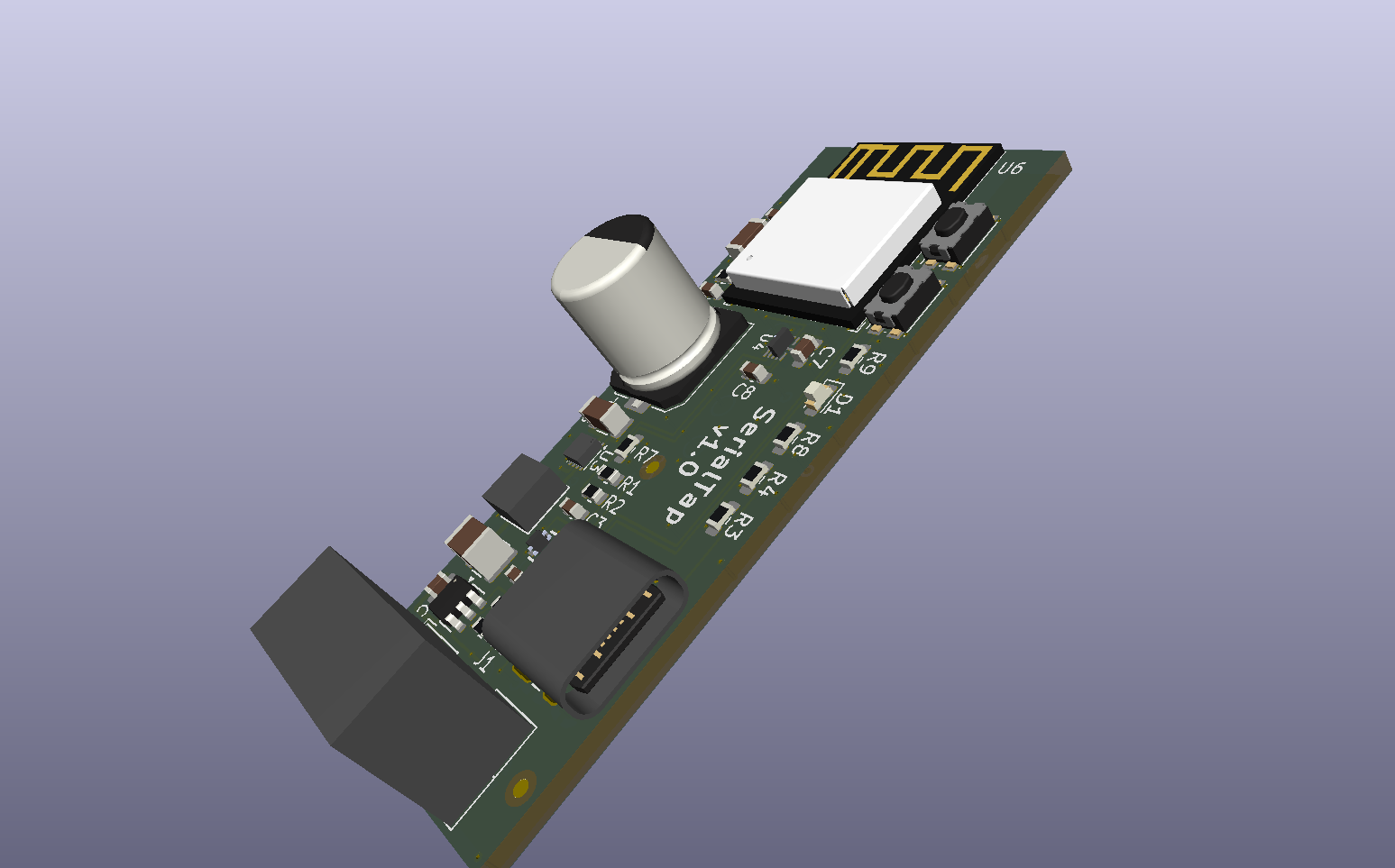
The reference target is a Haier AS50QDFHRA split-system air conditioner, whose service port speaks GE Appliances GEA3 at 230400 8N1 (docs/gea3.md). The board is not specialised to it: any appliance exposing 5 V and a UART on a service connector is in scope.
Version 1.0 has been sent to PCBWay; no board has been built yet. The
v1.0 tag marks the sources the order was built from.
Every design stage is done: power-path simulation, parts, library, schematic, layout and three review gates. What is still owed is measurement on the real appliance: the rail's current has so far been inferred, not measured (ADR 0007).
Service connector, as fitted to the reference appliance:
| Pin | 1 | 2 | 3 | 4 | 5 |
|---|---|---|---|---|---|
| Signal | 5 V | TX (board drives) | RX | spare (unknown) | GND |
| To understand… | Read |
|---|---|
| The vocabulary | CONTEXT.md |
| The design, end to end | docs/SPDD.md |
| Why it is this way | docs/adr/: seven decisions, each with its context and what would reverse it |
| The protocol | docs/gea3.md |
| How the schematic was checked | docs/schematic-capture.md |
| Layout rules and review gates | docs/layout-rules.md |
| Parts and sourcing | bom/README.md |
| Power-path simulation | sim/README.md |
| Bring-up and measurement | docs/bench-plan.md, docs/bench-results.md |
pcb/     KiCad 10 project: serialtap.kicad_sch / .kicad_pcb / .kicad_pro
lib/     the project's own symbols, footprints, 3D models and datasheets
sim/     LTspice power-path decks and their results
bom/     bill of materials and sourcing notes
docs/    design document, ADRs, protocol, layout and bench notes
bench/ capture and analysis scripts, and the ESPHome config used on the benchOpen pcb/serialtap.kicad_pro in KiCad 10. Everything it references is
in lib/ through ${KIPRJMOD}-relative paths, so it needs no global library.
CLI=/Applications/KiCad/KiCad.app/Contents/MacOS/kicad-cli   # macOS path
"$CLI" sch erc pcb/serialtap.kicad_sch
"$CLI" pcb drc --schematic-parity pcb/serialtap.kicad_pcb
The simulations need LTspice and vendor models that are not redistributed here; sim/README.md explains how to get them.
Fabrication outputs are regenerated rather than committed. Each fab order is tagged, so a physical board traces back to its sources.
Hardware under CERN-OHL-P v2; firmware and documentation under MIT. Both are permissive. NOTICE sets out which files fall under which, and the third-party material that falls under neither.
| Qty | Value | Footprint | References |
|---|---|---|---|
| 10 | TestPoint | serialtap:TestPoint_Pad_D1.5mm | TP1, TP2, TP3, TP4, TP5, TP6, TP7, TP8, TP9, TP10 |
| 4 | 0.1u | serialtap:C_0603_1608Metric | C1, C7, C8, C9 |
| 3 | 1u | serialtap:C_0603_1608Metric | C2, C3, C11 |
| 3 | 5.1k | serialtap:R_0603_1608Metric | R3, R4, R8 |
| 3 | Fiducial_1mm_Mask2mm | serialtap:Fiducial_1mm_Mask2mm | FID1, FID2, FID3 |
| 2 | 100k | serialtap:R_0603_1608Metric | R6, R7 |
| 2 | 10u | serialtap:C_1206_3216Metric | C5, C10 |
| 2 | 330 | serialtap:R_0603_1608Metric | R1, R2 |
| 2 | SW_Push | serialtap:SW_Push_1P1T_NO_CK_KMR2 | SW1, SW2 |
| 1 | 10k | serialtap:R_0603_1608Metric | R10 |
| 1 | 2.2k | serialtap:R_0603_1608Metric | R9 |
| 1 | 22u | serialtap:C_1210_3225Metric | C6 |
| 1 | 66.5k | serialtap:R_0603_1608Metric | R5 |
| 1 | B05B-XASK-1-A | serialtap:JST_XA_B05B-XASK-1-A_1x05_P2.50mm_Vertical | J1 |
| 1 | ESP32-C3-MINI-1 | serialtap:ESP32-C3-MINI-1 | U6 |
| 1 | LED | serialtap:LED_0603_1608Metric | D1 |
| 1 | LM66200DRL | serialtap:TI_DRL0008A_SOT-5X3-8_2.1x1.6mm_P0.5mm | U2 |
| 1 | PCL1A471MCL1GS | serialtap:CP_Elec_8x10 | C4 |
| 1 | TPD4E05U06DQA | serialtap:USON-10_2.5x1.0mm_P0.5mm | U5 |
| 1 | TPS2553DBV | serialtap:SOT-23-6 | U1 |
| 1 | TPS62162DSG | serialtap:Texas_DSG0008A_WSON-8-1EP_2x2mm_P0.5mm_EP0.9x1.6mm_ThermalVias | U3 |
| 1 | TXU0204RUT | serialtap:TI_RUT0012A_UQFN-12_2.0x1.7mm_P0.4mm | U4 |
| 1 | USB4085-GF-A | serialtap:USB_C_Receptacle_GCT_USB4085 | J2 |
| 1 | XGL4020-222MEC | serialtap:L_Coilcraft_XGL4020_4.0x4.0mm | L1 |
It measures 54 × 22 mm and has 4 copper layers, 1.6 mm thick.
46 parts, built around the ESP32-C3-MINI-1-H4X, TPS62162DSGT, LM66200DRL and TPD4E05U06QDQARQ1. The full list of its parts is on this page, with links to each part's symbol and footprint where PCBKit's library has them.
From the tfindlay-au/SerialTap repository on GitHub, at the commit this page was made from: the board is pcb/serialtap.kicad_pcb and its schematic pcb/serialtap.kicad_sch. PCBKit opens the board in the browser, with nothing to install.
Its repository publishes it under the CERN-OHL-P-2.0 licence: you may reuse it on that licence's terms (keep the author's notice, and for a copyleft licence share your changes alike).
zeugmaster/nucula-board
Nucula Board: an ESP32-C3 hardware prototype with USB-C, PN7160 NFC, OLED and detachable keyboard. KiCad sources and manufacturing files.

hlord2000/Sidewalk_Devkit
KiCad hardware design for a compact Nordic Semiconductor devkit built around an nRF54L15 target, nPM1300 power management, and an SX1262 sub-GHz radio front end.

OpenParol/OpenParol-Board
Open-source project for a 6-DOF robotic arm controller

antmicro/jetson-orin-baseboard
Baseboard targetting the NVIDIA Jetson Orin Nano and Jetson Orin NX

antmicro/jetson-agx-thor-baseboard
Open hardware baseboard for Nvidia Jetson Thor AGX T5000 System on Module

antmicro/kintex-410t-devboard
This repository contains open hardware design files for a devkit created for AMD-Xilinx Kintex-7 K410T FPGA.

antmicro/rdimm-ddr5-tester
FPGA-based DRAM tester supporting RDIMM DDR5 memories

antmicro/dc-scm-osm-l-carrier-card
DC-SCM Card supporting OSM-L System on Modules