4 layers65 × 75 mm

 testudor/shutdown-manager-mainboard1
Power input module for 3D printers capable of performing safe shutdown procedures for SBCs like Raspberry PIs
Shutdown manager mainboard is an open-source printed circuit board by testudor, from the testudor/shutdown-manager-mainboard repository on GitHub, published under the CC-BY-SA-4.0 licence. It is a 2-layer board of 84.3 × 39.4 mm with 28 parts on 30 nets, routed with 146 tracks and 14 vias.
It is built around the IRM-02-12, DRV8220DSG and TPS76133DBV, with the CL05B104KO5NNN, 0402WGF1002 and CL10A106MA8NRN among its other parts. Its parts include 9 capacitors, 4 ICs, 4 connectors, 3 resistors and 1 switch. It belongs with the computers and single-board computers and robots and motor control boards and the SAM D and SAM boards of this library.


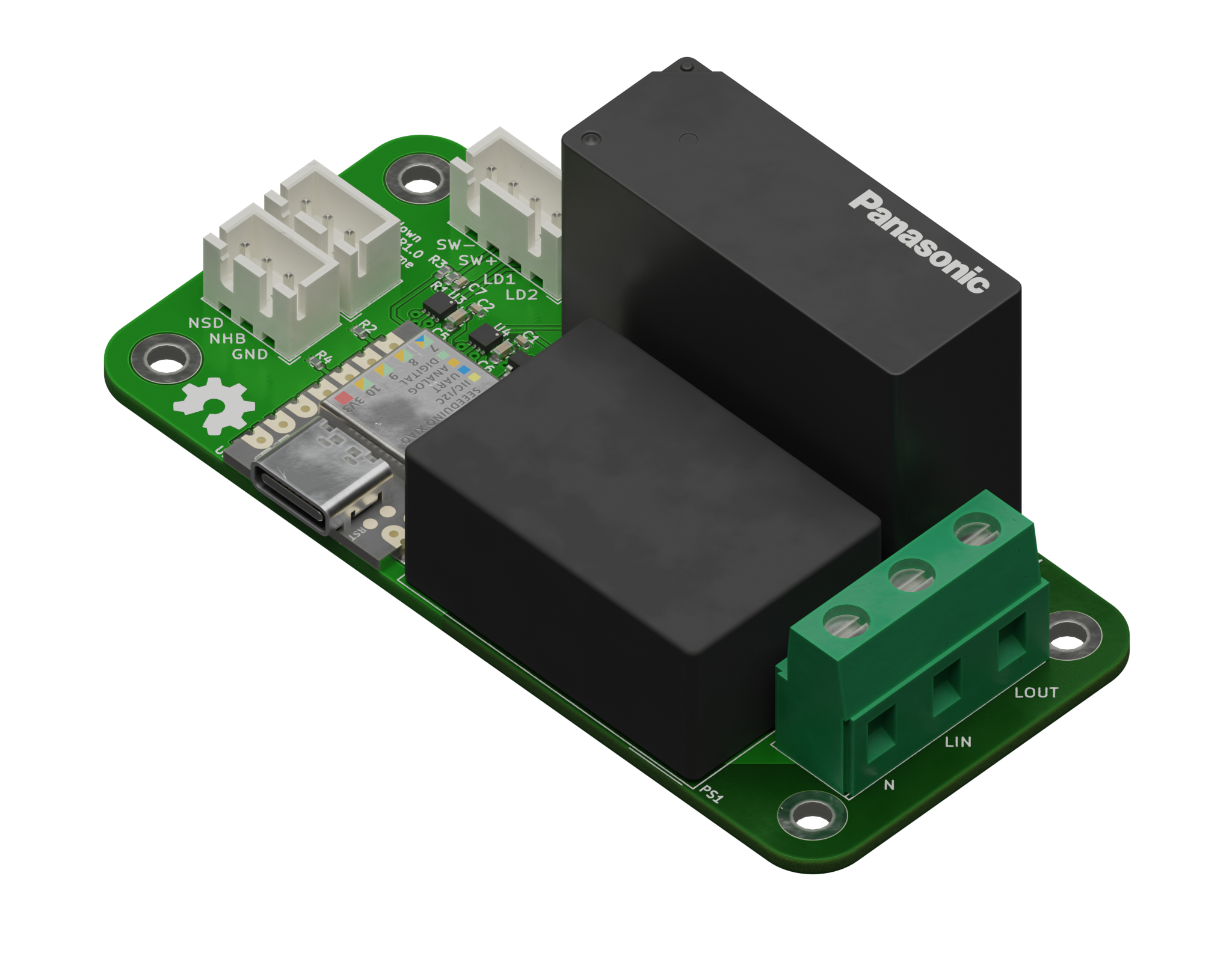
This is a board for switching the AC mains input in machines such as 3D printers or CNC machines.
It is designed to be controlled by a push button switch with built-in dual color LEDs. An on-board LED driver controls these LEDs and different light patterns indicate the current system status.
The board has connections for two "nodes". These are external devices that require a safe shutdown procedure, such as a Raspberry Pi. It will trigger a shutdown of the nodes and will not turn off the power until they have completely shut down.
It is specifically designed to handle high inrush currents from SMPSs, which can cause normal relays to have their contacts weld together.
| Pin | Function |
|---|---|
| NSD | Node Shutdown - is repeatedly cycled low and high to trigger a shutdown of external devices |
| NHB | Node Heart Beat - should be driven HIGH, when a node is running and LOW when it's shut down. |
For an easy way to connect a Raspberry Pi see this repo.
| Pin | Function |
|---|---|
| SW-/SW+ | Connected to the power switch. |
| LD1/LD2 | Connected to the switches' dual color LED. |
I can recommend the ONPOW GQ19F-10E/RG/12/S, however any push button switch with 12V dual color LEDs should work. By dual color I mean LEDs which change their color based on polarity.
All necessary files can be found in the release section. They are compatible with the usual fab houses.
To use the full 16A this board was designed for, get 2oz PCBs or liberally coat the mains voltage traces on the bottom in solder.
I'm leaving these instructions intentionally vague as this is NOT a beginner's project. The more experienced should know what to do.
This board requires firmware to be flashed and configured. For details see this repo.
WARNING:
This board was designed to the best of my knowledge, but I am NOT an electrical engineer. If you decide to build this, I am not liable for damages or harm to yourself or anyone else.
| Qty | Value | Footprint | References |
|---|---|---|---|
| 5 | 0.1uF | Capacitor_SMD:C_0402_1005Metric | C1, C2, C7, C8, C9 |
| 4 | MountingHole | MountingHole:MountingHole_3.2mm_M3_ISO7380_Pad_TopBottom | H1, H2, H3, H4 |
| 3 | 10k | Resistor_SMD:R_0402_1005Metric | R1, R3, R5 |
| 2 | 10uF | Capacitor_SMD:C_0603_1608Metric | C5, C6 |
| 2 | Conn_01x03 | Connector_JST:JST_XH_B3B-XH-A_1x03_P2.50mm_Vertical | J2, J3 |
| 2 | DRV8220DSGR | Package_SON:WSON-8-1EP_2x2mm_P0.5mm_EP0.9x1.6mm | U3, U4 |
| 1 | 1uF | Capacitor_SMD:C_0402_1005Metric | C3 |
| 1 | 4.7uF | Capacitor_SMD:C_0603_1608Metric | C4 |
| 1 | Conn_01x03 | Custom_Connectors:282844-3 | J6 |
| 1 | Conn_01x04 | Connector_JST:JST_XH_B4B-XH-A_1x04_P2.50mm_Vertical | J1 |
| 1 | IRM-02-12 | Converter_ACDC:Converter_ACDC_MeanWell_IRM-02-xx_THT | PS1 |
| 1 | Relay_SPST_Panasonic_DJH-FormA-Single-Coil | Custom_Relay:Relay_SPST_Panasonic_DJH-FormA-Single-Coil | K1 |
| 1 | Seeed Studio XIAO SAMD21 | Seeed Studio XIAO Series Library:XIAO-SAMD21-RP2040-14P-2.54-21X17.8MM (Seeeduino XIAO) | U1 |
| 1 | TPS76133DBVR | Package_TO_SOT_SMD:SOT-23-5 | U2 |
The 26 most common of 28 parts.
It measures 84.3 × 39.4 mm and has 2 copper layers, 1.67 mm thick.
28 parts, built around the IRM-02-12, DRV8220DSG, TPS76133DBV and CL05B104KO5NNN. The full list of its parts is on this page, with links to each part's symbol and footprint where PCBKit's library has them.
From the testudor/shutdown-manager-mainboard repository on GitHub, at the commit this page was made from: the board is Shutdown Manager Mainboard.kicad_pcb and its schematic Shutdown Manager Mainboard.kicad_sch. PCBKit opens the board in the browser, with nothing to install.
Its repository publishes it under the CC-BY-SA-4.0 licence: you may reuse it on that licence's terms (keep the author's notice, and for a copyleft licence share your changes alike).


kaminaris/GigaESC-Power200V
Compact 50 × 20 mm non-isolated power-supply module for the modular GigaESC platform, intended for the 200 V version. Provides 12 V, 5 V and 3.3 V rails through a separate output connector.

elagil/net-bmp
An Ethernet-connected SWD/JTAG debug adapter (blackmagic probe)

matthiasnowak/jewelled
This is a panel meant for production of the Earrings, allowing for 2 Earrings per panel.


kaminaris/GigaESC-ControlBoard
Compact six-layer control card for modular GigaESC motor controllers. The MCU, CAN transceiver, IMU and signal conditioning live here; the MOSFET power stage and power supply are separate boards.
