
4 layers42 × 42 mm

 Teslafly/TLE5012-Hall-Encoder-Module7
Breakout/mounting board for the TLE5012 hall encoder for vesc
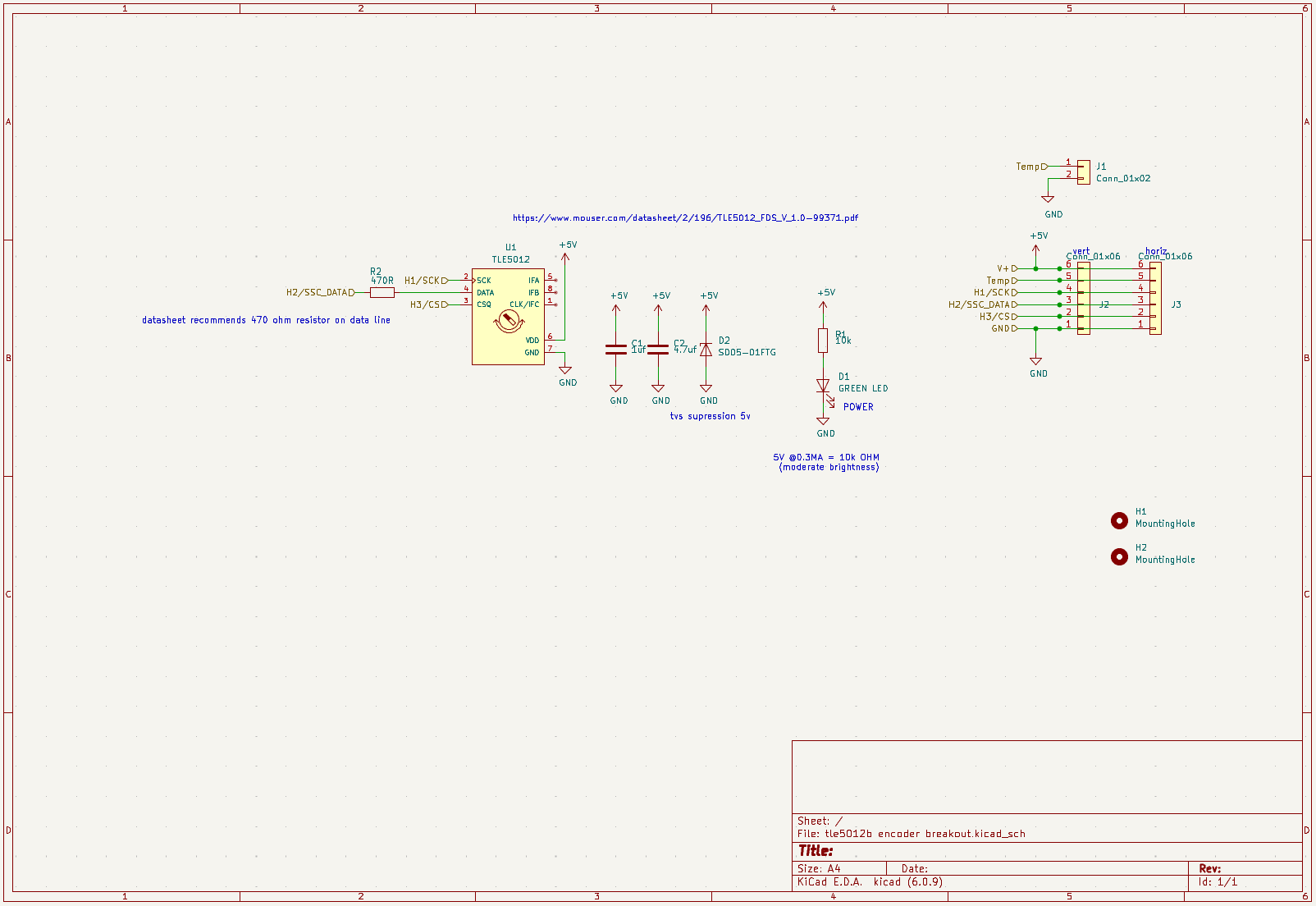
Tle5012b encoder breakout is an open-source printed circuit board by Teslafly, from the Teslafly/TLE5012-Hall-Encoder-Module repository on GitHub. It is a 2-layer board with 12 parts on 11 nets, routed with 65 tracks and 9 vias.
It is built around the TLE5012 and SD05-01FTG. Its parts include 3 connectors, 2 capacitors, 2 resistors, 2 diodes and 1 IC. It belongs with the interfaces and adapters boards of this library.
Breakout/mounting board for the TLE5012 hall encoder to use with the vesc motor controller project.
(Pictures are from my nearly identical as5047 encoder board at https://github.com/Teslafly/AS5047-Hall-Encoder-Module)
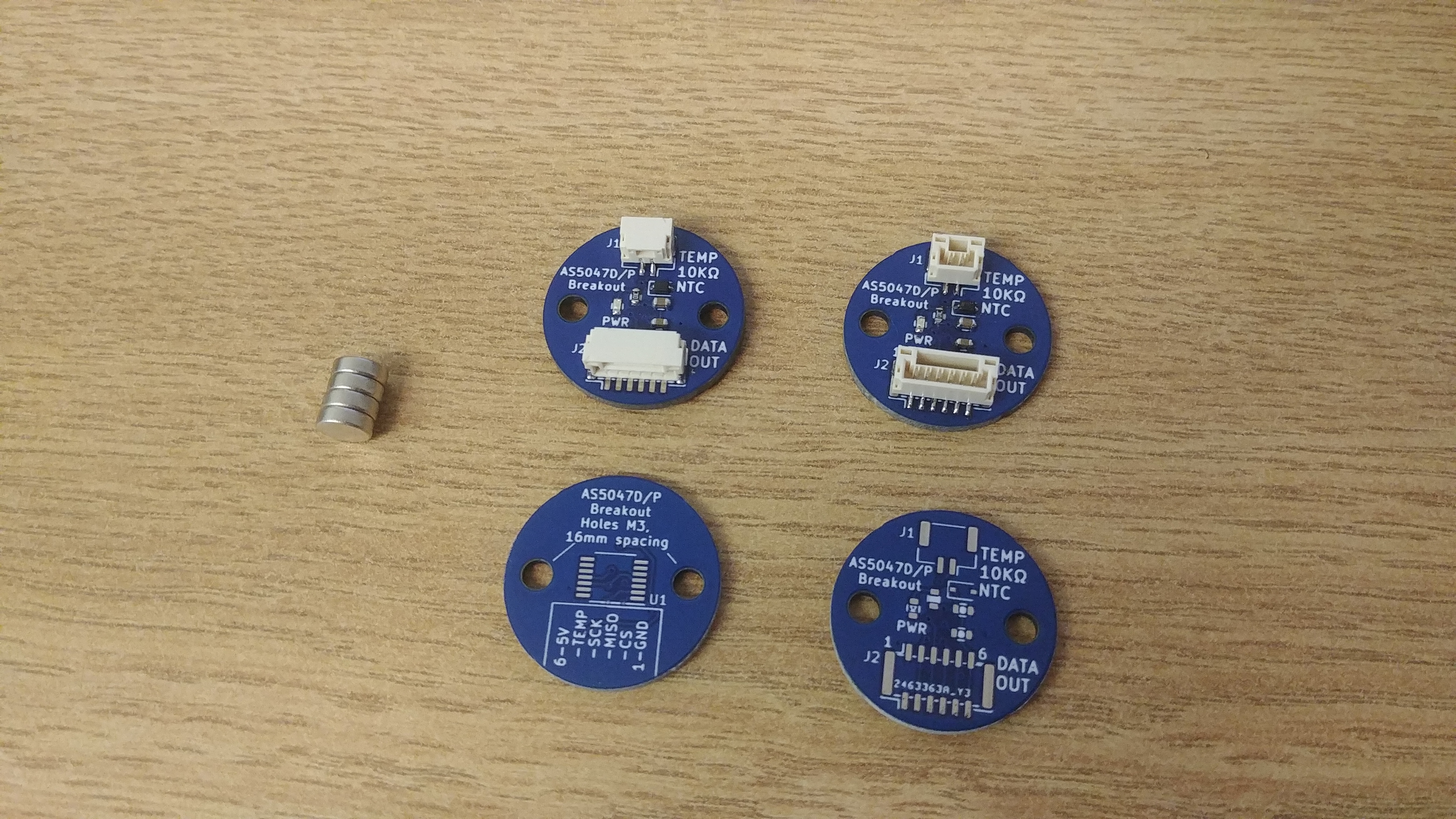
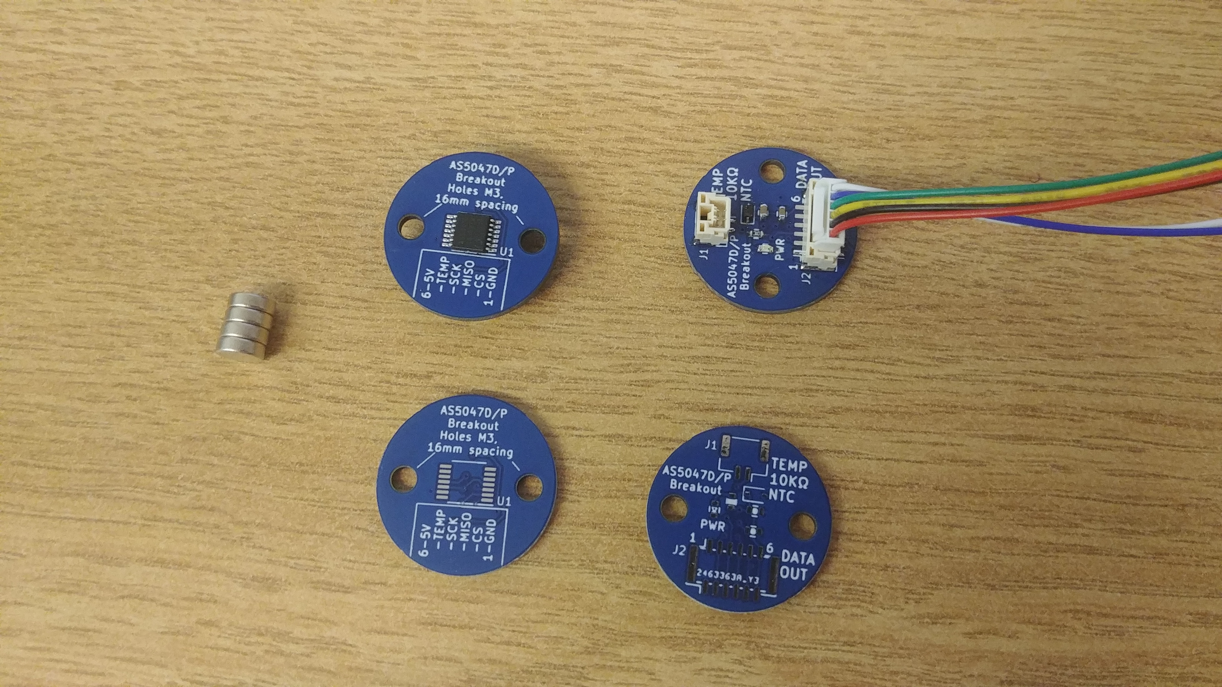
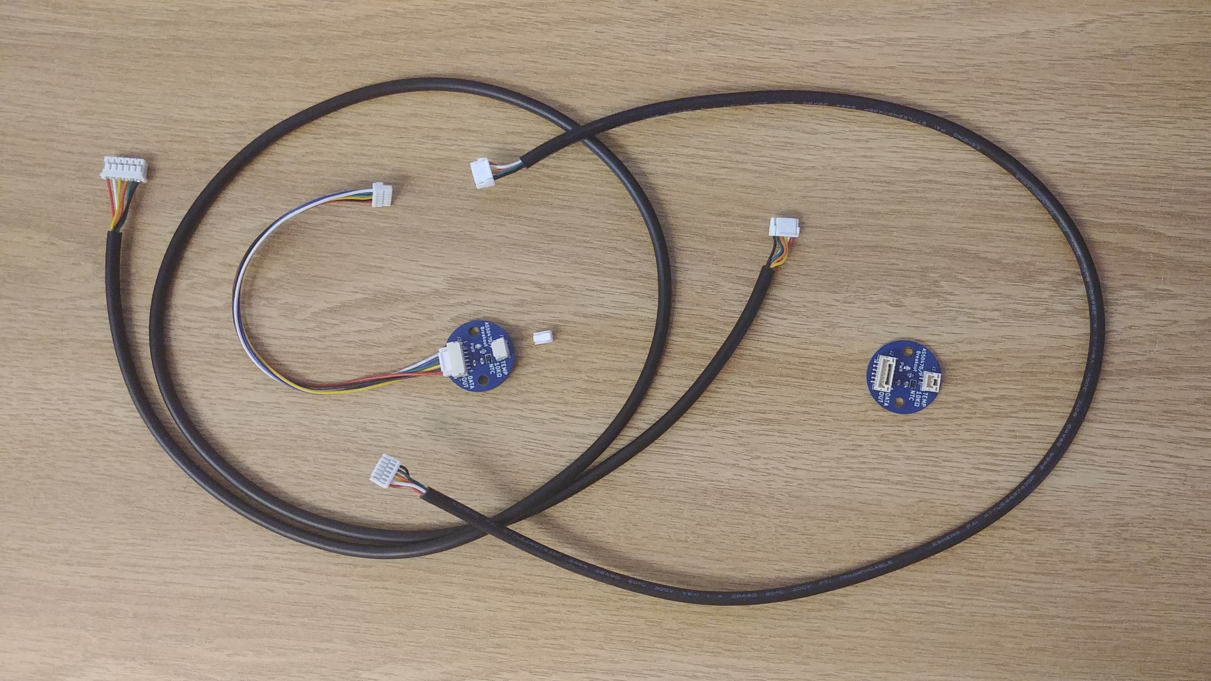
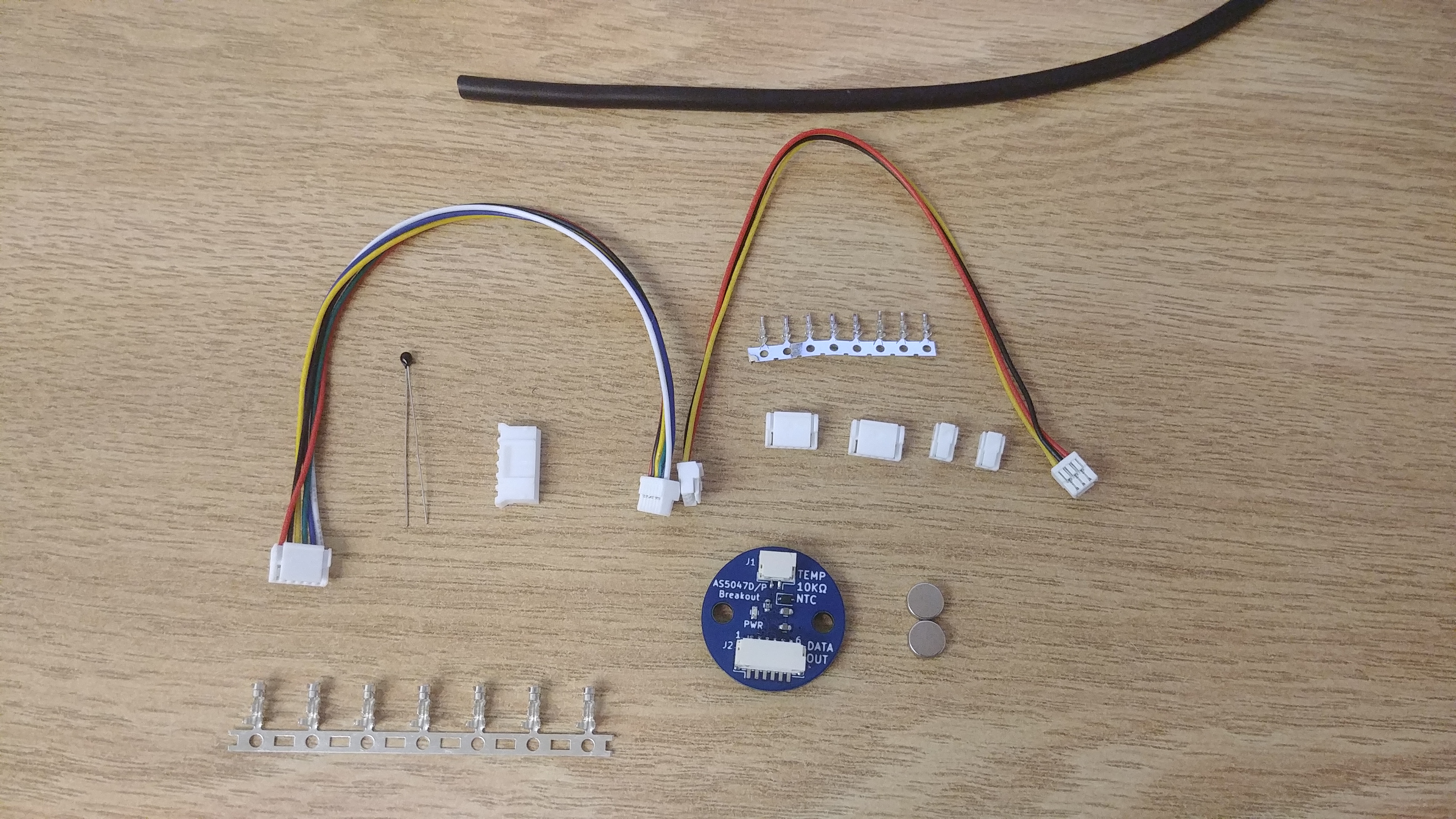
If you do not have a crimper for JST GH crimps, they are fiddley and are hard to crimp properly. I recommend either getting a male to male JST GH cable and cutting it to splice into a longer encoder cable, or doing the same with a precrimped silicone wire kit like this:
The jst gh data connector has the same pinout as the JST PH vesc hall sensor connector. however, note that some vesc hardwares that have swapped to JST GH connectors have reversed pinouts. aka the cable must connect pins 1<->6, 2<->5, etc so that the locking clips are reversed from each other.
Also, your vesc hardware must not have filters placed on the hall port pins. these filters must be removed for this encoder to work if present. They are present on all vesc hw 4.2, and nearly all flipsky boards. Trampa hw 6.0+ do not have these filters and will work as is.
I recommend using sheilded wire. usb cable will work in a pinch if you omot the temp wire and use the sheild for gnd. but ~28awg 6 core sheilded cable is ideal. the sheild should be connected to the gnd pin on the vesc side, and unconnected on the sensor side. you must keep all wires close to each other to get good signal integrity when splicing /crimping the end connectors. If you cannot source sheilded wire, you will get acceptable results by keeping the wires close, and routing the cable away from the phase wires of the motor. It is recommended that the data cable is kept under 0.5 meters. If that is not possible then sheilded wire must be used and attention to detail excercised in cable construction.
This sensor runs best at 5V input power. 3.3V operation is not gaurenteed but will not cause damage.
The led on the pcb should glow somewhat dimly. It is not blindingly bright.
The sensor IC should get lukewarm during operation. If it gets really hot then it's dead or a wire is shorted
You can troubleshoot/test the signal integrity of your cable and encoder functionality with the "encoder" command in the vesc terminal.
when viewing the encoder angle in the vest-tool realtime view, the encoder value should change smoothly through the entire 360 degrees. If it is jumpy you probably have a signal integrity issue
If the sensor cable is poorly routed/sheilded, high motor currents can cause noise that increases the encoder error rate. If you experience encoder faults during acceleration, check for intermittent opens in all signals and try rerouting the sensor cable away from motor phase wires and battery cables.
a 3d printable test jig using a 608 bearing and 6mm magnet is included in the "608 bearing test holder" folder.
| Qty | Value | Footprint | References |
|---|---|---|---|
| 2 | MountingHole | MountingHole:MountingHole_3.2mm_M3 | H1, H2 |
| 1 | 10k | pkl_dipol:R_0603 | R1 |
| 1 | 1uf | pkl_dipol:C_0603 | C1 |
| 1 | 4.7uf | pkl_dipol:C_0603 | C2 |
| 1 | 470R | pkl_dipol:R_0603 | R2 |
| 1 | Conn_01x02 | Connector_JST:JST_GH_SM02B-GHS-TB_1x02-1MP_P1.25mm_Horizontal | J1 |
| 1 | GREEN LED | pkl_dipol:D_0603 | D1 |
| 1 | SD05-01FTG | Diode_SMD:D_SOD-323 | D2 |
| 1 | TLE5012 | Package_SO:SO-8_3.9x4.9mm_P1.27mm | U1 |
| 1 | data-H | Connector_JST:JST_GH_SM06B-GHS-TB_1x06-1MP_P1.25mm_Horizontal | J3 |
| 1 | data-V | Connector_JST:JST_GH_BM06B-GHS-TBT_1x06-1MP_P1.25mm_Vertical | J2 |
12 parts, built around the TLE5012 and SD05-01FTG. The full list of its parts is on this page, with links to each part's symbol and footprint where PCBKit's library has them.
From the Teslafly/TLE5012-Hall-Encoder-Module repository on GitHub, at the commit this page was made from: the board is tle5012b encoder breakout.kicad_pcb and its schematic tle5012b encoder breakout.kicad_sch. PCBKit opens the board in the browser, with nothing to install.
Its repository states no licence, so its author keeps all rights: ask Teslafly before reusing the design.

Teslafly/MT6816CT-encoder-breakout
MT6816CT encoder breakout for vesc


ut-ims-robotics/eensaar-thesis-2026-wireless-finish-punch-transmission
This repository hosts the source code, electrical schematics and layout, as well as documentation developed by Emil Eensaar for his Bachelor of Science thesis.

Chicken-Fried/STM32-NanoCortex
Ultra-compact USB-C development board powered by STM32F042 (ARM Cortex-M0) with native DFU, ceramic-only LDO power stage & CaveRover branding.

github-linguist/linguist
Language Savant. If your repository's language is being reported incorrectly, send us a pull request!


google/mozc-devices
Circuit diagrams and firmware source code for Gboard DIY keyboards