
4 layers67.5 × 9.2 mm
Ref mic
loudifier/OpenRefMic
open hardware design for a high-performance low-cost measurement microphone
47 parts169MIT

 teisenbe/transpsoe4
1u pitch transposition module for Eurorack
Transpsoe is an open-source printed circuit board by teisenbe, from the teisenbe/transpsoe repository on GitHub. It is a 2-layer board of 102.3 × 51 mm with 107 parts on 93 nets, routed with 742 tracks and 71 vias.
It is built around the OPA4991ID. Its parts include 64 resistors, 15 connectors, 14 capacitors, 6 ICs and 3 diodes. It belongs with the audio and music boards of this library.
This is a Eurorack 1u 22hp module that performs pitch transposition on V/oct signals. Outputs are accurate to within 1.5mV, often better. The panel is designed for Intellijel 1u, but is (untested) compatible with Pulp Logic 1u. Build instructions can be found here. Note: revs 1 and 2 have not been built yet. Rev 1 but is only minor changes from rev 0, but 2 is more substantial. See the changelog for details.
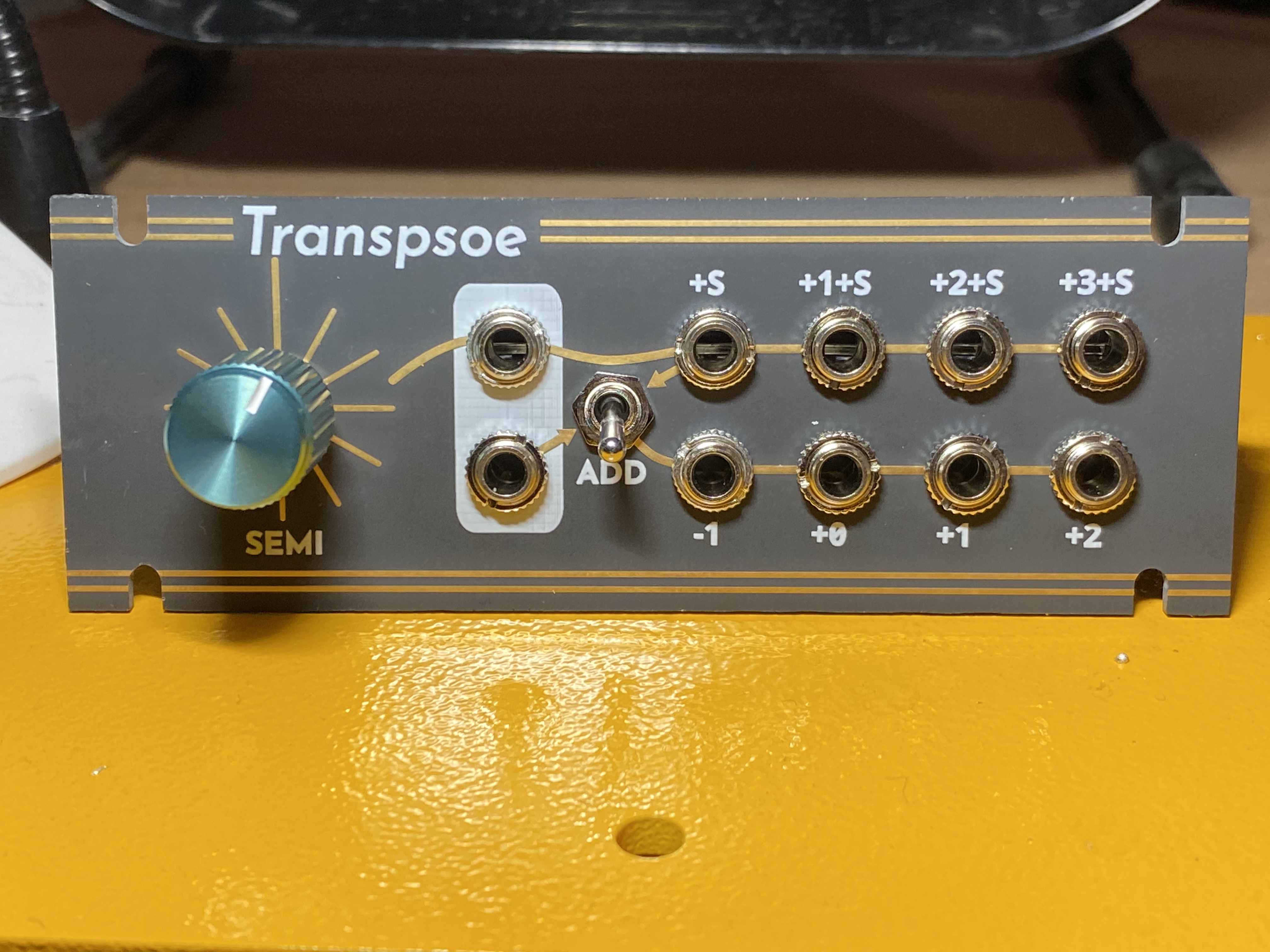
Transpsoe has two inputs, 8 outputs, a toggle switch, and a rotary knob. The two rows of jacks corresponds roughly to two channels of operation.
The inputs are identified by white outlines. The jacks are both normed to 0V. Each input is fed to the jacks to their right. The channel summing mechanism can also feed the top input downward.
The toggle switch can be used to bridge the two channels. If the toggle switch is in the down position, pointing toward the "ADD" label, then the bottom outputs behaves as if the bottom input is increased by the top input and the semitone transposition.
The rotary knob selects semitone transposition in 12-TET. 0 semitones corresponds to the vertical position, with the extra long radial line. The number of semitones increases by 1 as you move clockwise. Semitone transposition applies only to the first channel unless channel summing is enabled.
Each output is labeled with an integer representing a number of octaves to shift up the channel's input by. The top channel is also shifted up by the number of semitones selected on the knob.
All inputs should function fine in the +/- 11V range. All outputs should function fine as long as their expected value is in the +/- 11V range.
The circuit generates a 4.096V +/- 0.1% reference using a shunt diode. A resistor divider with a trimpot is used to get a 4V reference. -1V, 1V, 2V, and 3V references are generated from the 4V reference.
| Qty | Value | Footprint | References |
|---|---|---|---|
| 30 | 100k | Resistor_SMD:R_0603_1608Metric_Pad0.98x0.95mm_HandSolder | R10, R11, R12, R13, R14, R16, R20, R21, R22, R23, R28, R29, R30, R31, R32, R33 +14 |
| 13 | 10k | Resistor_SMD:R_0603_1608Metric_Pad0.98x0.95mm_HandSolder | R69, R71, R72, R73, R74, R75, R76, R77, R78, R79, R80, R81, R82 |
| 10 | 100nF | Capacitor_SMD:C_0603_1608Metric_Pad1.08x0.95mm_HandSolder | C1, C2, C3, C4, C5, C6, C7, C8, C9, C10 |
| 10 | AudioJack2_SwitchT | transpsoe:PJ-301BM | J1, J2, J3, J4, J5, J6, J8, J9, J10, J11 |
| 8 | 330 | Resistor_SMD:R_0603_1608Metric_Pad0.98x0.95mm_HandSolder | R24, R25, R26, R27, R44, R45, R46, R47 |
| 5 | 1k | Resistor_SMD:R_0603_1608Metric_Pad0.98x0.95mm_HandSolder | R53, R55, R56, R57, R58 |
| 5 | OPA4991 | Package_SO:SOIC-14_3.9x8.7mm_P1.27mm | U1, U2, U3, U5, U6 |
| 2 | 10uF (>=25V) | Capacitor_SMD:C_0603_1608Metric_Pad1.08x0.95mm_HandSolder | C13, C14 |
| 2 | 1M | Resistor_SMD:R_0603_1608Metric_Pad0.98x0.95mm_HandSolder | R1, R2 |
| 2 | 2k | Potentiometer_THT:Potentiometer_Bourns_3296W_Vertical | RV1, RV2 |
| 2 | Conn_01x08_Female | transpsoe:SAMTEC_SSM-108-L-SV-LC | J12, J13 |
| 2 | Conn_01x08_Male | transpsoe:SAMTEC_TSM-108-01-F-SV-LC | J14, J15 |
| 2 | DNI | Capacitor_SMD:C_0603_1608Metric_Pad1.08x0.95mm_HandSolder | C11, C12 |
| 2 | D_Schottky | Diode_SMD:D_SMA_Handsoldering | D1, D2 |
| 1 | 110k | Resistor_SMD:R_0603_1608Metric_Pad0.98x0.95mm_HandSolder | R67 |
| 1 | 1N4148 | Diode_SMD:D_SOD-123 | D3 |
| 1 | 22k | Resistor_SMD:R_0603_1608Metric_Pad0.98x0.95mm_HandSolder | R48 |
| 1 | 39k | Resistor_SMD:R_0603_1608Metric_Pad0.98x0.95mm_HandSolder | R50 |
| 1 | 3k | Resistor_SMD:R_0603_1608Metric_Pad0.98x0.95mm_HandSolder | R52 |
| 1 | 820 | Resistor_SMD:R_0603_1608Metric_Pad0.98x0.95mm_HandSolder | R70 |
| 1 | 9.1k | Resistor_SMD:R_0603_1608Metric_Pad0.98x0.95mm_HandSolder | R68 |
| 1 | Conn_02x05_Odd_Even | Connector_PinHeader_2.54mm:PinHeader_2x05_P2.54mm_Vertical | J7 |
| 1 | G*** | transpsoe:raccoon-7.5 | svg2mod |
| 1 | LM4040DBZ-4.1 | Package_TO_SOT_SMD:SOT-23 | U4 |
| 1 | SW_Rotary12 | transpsoe:MC12xxxCxx | SW1 |
| 1 | SW_SPDT | transpsoe:BNT11SEA5QE | SW2 |
loudifier/OpenRefMic
open hardware design for a high-performance low-cost measurement microphone


wntrblm/Helium
Helium is a triple 1-to-3 precision buffered multiple and 3-to-1 precision adder


zueblin/Polaron
A DIY drum machine for the teensy microcontroller (hardware / software)

It measures 102.3 × 51 mm and has 2 copper layers, 1.6 mm thick.
107 parts, built around the OPA4991ID. The full list of its parts is on this page, with links to each part's symbol and footprint where PCBKit's library has them.
From the teisenbe/transpsoe repository on GitHub, at the commit this page was made from: the board is hardware/transpsoe.kicad_pcb and its schematic hardware/jack-board.kicad_sch. PCBKit opens the board in the browser, with nothing to install.
Its repository states no licence, so its author keeps all rights: ask teisenbe before reusing the design.