8 layers90.5 × 49.5 mm

 teehee567/Aevia5
gnss module collecting track data
V1 pcb is an open-source printed circuit board by teehee567, from the teehee567/Aevia repository on GitHub. It is a 4-layer board of 56 × 20.5 mm with 21 parts on 35 nets, routed with 132 tracks and 28 vias.
It is built around the NEO-M9V-20B, AP2112K-3.3TRG1 and MCP73831T-2ACI/OT-HXY, with the RC0805FR-0710KL, CL21A475KAQNNNE and LQG15HN27NJ02D among its other parts. Its parts include 7 capacitors, 5 resistors, 4 ICs, 1 diode and 1 connector. It belongs with the radio and wireless boards and the nRF52 and nRF5x boards of this library.


Aevia is a DIY, battery powered lap timer and track data logger. The current hardware is the V2 Mini, a compact board that combines multi-band GNSS, a 6-axis IMU, local storage, a display interface, physical controls, and wireless connectivity.
Uses very very high end sensors, UM980, SCH16T-K01
The goal is to build something in the same general space as a Garmin Catalyst, but at a lower cost and with more control over the hardware, raw data, and software. Recorded data should also remain useful outside the device, with export to proper desktop analysis tools.
The V2 Mini is built around:
ESP32-S31-WROOM-3-N16R16V as the main processor and radioUM980 multi-band, multi-constellation GNSS receiverSCH16T-K01-1 6-axis accelerometer and gyroscopeSee v2_mini_design.md for the block diagrams, power tree, fitted parts, and current one-off build estimate.
The base firmware now provides structured hardware
bring-up and a button-free J6 USB flash runner. From firmware/, run
cargo run --release --locked to build, flash and verify the restart.
The immediate work is hardware bring-up and the basic firmware needed to read the GNSS and IMU, store sessions on the microSD card, and exercise the display and controls. The application backlog currently looks like this.
Of the modules considered, the UM980 is the best fit I found for raw GNSS quality at this price. It can output at 20 Hz while using multiple GNSS constellations. That matters in a car because an antenna inside the windscreen loses much of its view behind the metal roof. Combining GPS, GLONASS, Galileo, and BeiDou leaves more satellites available for each fix and can improve accuracy when the view of the sky is limited. A receiver advertised as "multi-GNSS" does not necessarily support its maximum update rate while using several constellations at once.
It also supports multiple frequency bands. A single-band receiver has a harder time separating a direct signal from one reflected by the car or nearby barriers. Comparing L1 with L2 or L5 gives the receiver more information for rejecting poor measurements.
The planned BT-T076 is a wide multi-band active helical antenna, although its sheet does not explicitly document every UM980 signal. Helical designs generally tolerate tilt and an uncertain ground plane better than conventional patches, but the BT-T076 datasheet does not publish the angular, per-band patterns needed to rank it against a particular patch. A correctly integrated patch that covers every required band may provide cleaner measurements in a fixed installation; many common patches are only L1 or depend on a specific ground plane. See the GNSS antenna decision note for the mounting scenarios, electrical constraints, expected data effects, and A/B test plan.
The expected gain over a decent off-the-shelf logger is not enormous, and software quality will matter just as much as the receiver. For absolute lap-time proof, a track transponder still wins.
These figures are working notes from the module research and should be checked again before buying parts.
| Receiver | Notes |
|---|---|
Unicore UM980 | L1, L2/L5, and L6; multi-constellation; full RTK; 20 Hz with full multi-GNSS; about 50 Hz in RTK mode; roughly A$130 |
u-blox NEO-M9N | L1-only; multi-constellation; 25 Hz with one constellation or 10 Hz with several; roughly A$20 |
u-blox NEO-M10S | L1-only; multi-constellation; 25 Hz with one constellation or 10 Hz with several; roughly A$20 |
u-blox ZED-F9P | L1 and L2; multi-constellation; full RTK; about 8 Hz with everything enabled or 20 Hz with a reduced configuration; roughly A$130 |
Quectel LC29H-DA/EA | L1 and L5; multi-constellation; RTK on the EA variant; 10 Hz maximum |
Septentrio mosaic-X5 | All bands and constellations; the best raw quality in this comparison; capable of 100 Hz; more than A$1,000 |
SkyTraq PX1122R | L1 and L2; multi-constellation RTK; apparently up to 20 Hz, although documentation and pricing were difficult to find |
The Dragy Pro was the only off-the-shelf product for which I could identify the receiver module. It uses a u-blox NEO-M10S and is listed in the research as 10 Hz with multiple constellations or 20 Hz with one. I have not found a module that clearly delivers 25 Hz, multi-GNSS, and 10 cm accuracy at the same time, so similar product claims are unlikely to be real.
The longer comparison is in data/gps_module_research.md. And raw GNSS modules specs are in data/GNSS_research.xlsx.
I do not recommend this as a first electronics build. Several parts need reflow equipment or a capable hot-air setup, and a one off board involves a fair amount of tooling and rework cost. The V2 Mini estimate is about $500AUD for the PCB, stencil, parts, GNSS receiver, antenna, and battery.
archive, old, bad
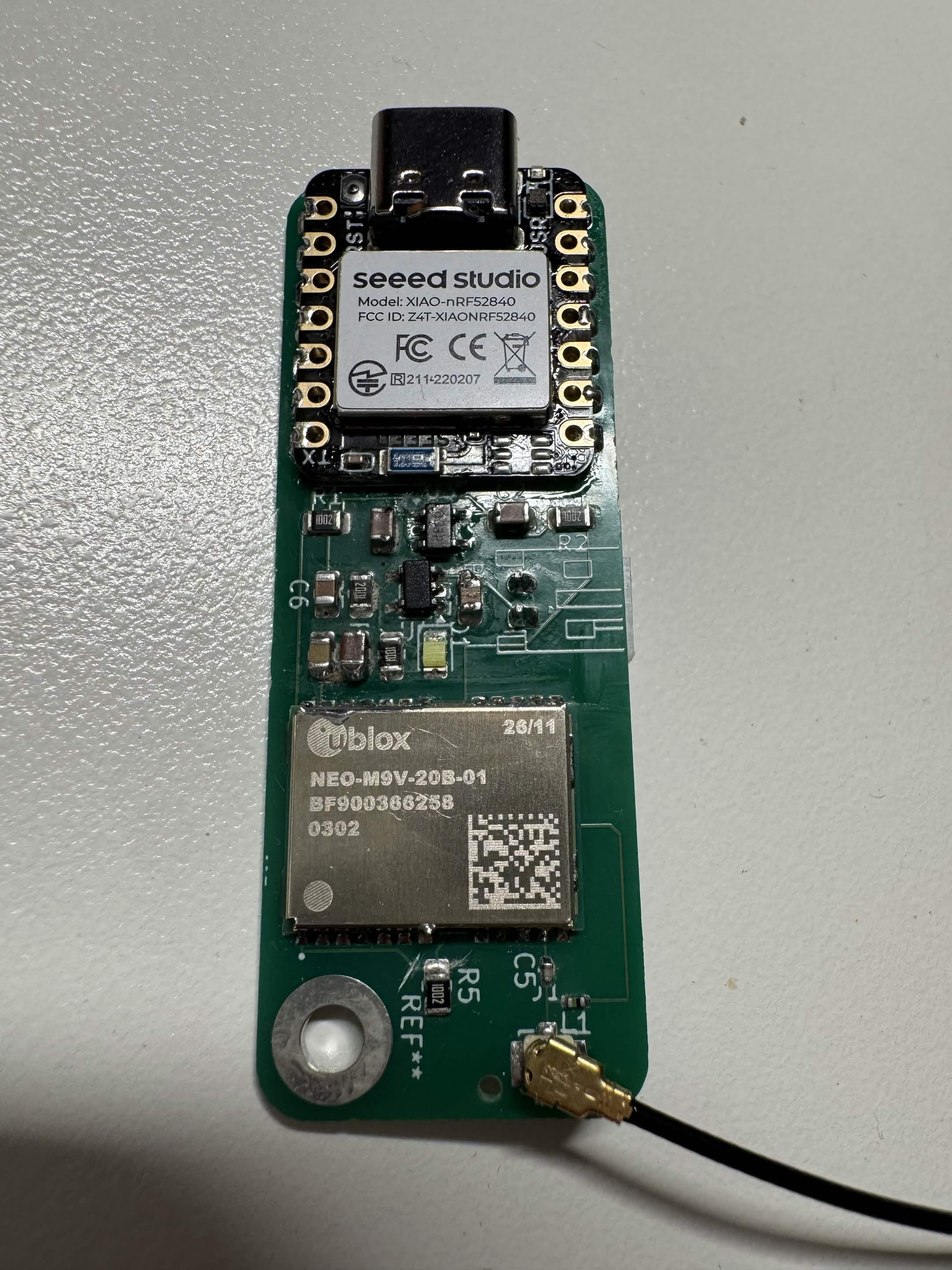
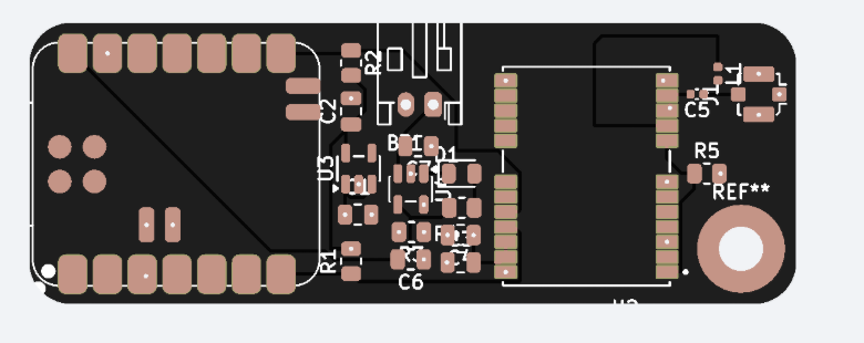
| Qty | Value | Footprint | References |
|---|---|---|---|
| 3 | 10k | Resistor_SMD:R_0805_2012Metric | R1, R2, R5 |
| 3 | 10uF | Capacitor_SMD:C_0805_2012Metric | C1, C2, C4 |
| 2 | 4.7uF | Capacitor_SMD:C_0805_2012Metric | C6, C7 |
| 1 | 0.1uF | Capacitor_SMD:C_0805_2012Metric | C3 |
| 1 | 1k | Resistor_SMD:R_0805_2012Metric | R4 |
| 1 | 27nH | Inductor_SMD:L_0402_1005Metric | L1 |
| 1 | 2k | Resistor_SMD:R_0805_2012Metric | R3 |
| 1 | 47pF | Capacitor_SMD:C_0402_1005Metric | C5 |
| 1 | AP2112K-3.3 | Package_TO_SOT_SMD:SOT-23-5 | U3 |
| 1 | Battery_Cell | Connector_JST:JST_PH_S2B-PH-K_1x02_P2.00mm_Horizontal | BT1 |
| 1 | Conn_Coaxial | Connector_Coaxial:U.FL_Molex_MCRF_73412-0110_Vertical | J1 |
| 1 | LED | LED_SMD:LED_0805_2012Metric | D1 |
| 1 | MCP73831-2-OT | Package_TO_SOT_SMD:SOT-23-5 | U4 |
| 1 | NEO-M9V-20B | NEO-M9V-20B:XCVR_NEO-M9V-20B | U2 |
| 1 | XIAO-nRF52840-SMD | New_XIAO_Series_Footprints:XIAO-nRF52840-SMD | U1 |
The 20 most common of 21 parts.
It measures 56 × 20.5 mm and has 4 copper layers, 1.6 mm thick.
21 parts, built around the NEO-M9V-20B, AP2112K-3.3TRG1, MCP73831T-2ACI/OT-HXY and RC0805FR-0710KL. The full list of its parts is on this page, with links to each part's symbol and footprint where PCBKit's library has them.
From the teehee567/Aevia repository on GitHub, at the commit this page was made from: the board is hardware/v1_pcb/pcb.kicad_pcb and its schematic hardware/v1_pcb/pcb.kicad_sch. PCBKit opens the board in the browser, with nothing to install.
Its repository states no licence, so its author keeps all rights: ask teehee567 before reusing the design.


SantiBarrios2002/mtp-f26-teamc
MTP F26 (UPC) Team C workspace: radio link budget, RFM69 firmware, protocol simulator

eihli/morse-mesh
This is the current hardware source for future Morse Mesh revisions. It is a professionally reviewed redraw of the frozen, fabricated v1 board, not a pin-compatible replacement: notably, KEYIN moved from v1 PA0 to v2…

lk-ek/esphome-unni-co2-sniffer
An esp32-c3 based passive data sniffer for Unni CO2 sensor devices

ollielarkins/pmd-tracker
Wearable rugby performance tracker: nRF52840 + Zephyr firmware, React Native companion app


ZigEmbeddedGroup/sycl-badge
The badge for the SYCL conference! https://zigembeddedgroup.github.io/sycl-badge/