
4 layers60 × 31 mm
GarageDoor pro
nikolaus018/garageDoor-pro
ESP32-C3 + GPS board that opens the garage door when you leave and arrive: firmware, KiCad PCB and perfboard build
46 parts1MIT

 ollielarkins/pmd-tracker
Wearable rugby performance tracker: nRF52840 + Zephyr firmware, React Native companion app
Pmd tracker is an open-source printed circuit board by ollielarkins, from the ollielarkins/pmd-tracker repository on GitHub. It is a 4-layer board of 45 × 30 mm with 31 parts on 82 nets, routed with 340 tracks and 82 vias.
It is built around the MAX-M10S-00B, MDBT50Q-1MV2 and ADXL372BCCZ-RL7, with the AP2112K-3.3TRG1, LSM6DSO and MCP73831T-2ACI/OT-HXY among its other parts. Its parts include 12 capacitors, 7 resistors, 6 ICs, 4 connectors and 2 diodes. It belongs with the wearables boards and the nRF52 and nRF5x boards of this library.


A wearable performance tracker for rugby. It sits in a jersey pouch between the shoulder blades, records a player's match, and syncs the results to a companion app for review after the game.
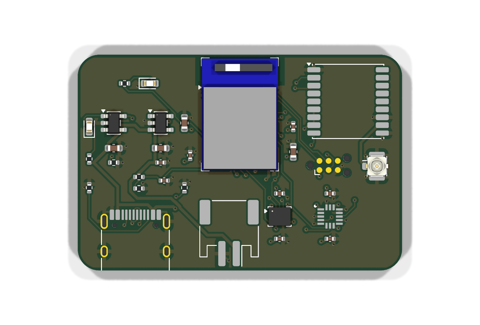
KiCad 3D render of the 45 x 30 mm 4-layer board (not yet fabricated).
| Area | Metrics |
|---|---|
| Locomotion | distance, max speed, sprint count and sprint distance |
| Contact load | impact count, peak g, total load, impacts by intensity band |
| Position | time-on-pitch heatmap (10 m cells), work rate in m/min |
firmware/lib/metrics, which is portable C:
PMD. The app reads one 228-byte summary characteristic (layout in metrics.h). It writes the reset characteristic to start a new session.Every threshold above sits in one pmd_config struct. They are starting values and still need calibrating against real sessions.
The device is designed against World Rugby Law 4.3(m), Regulation 12 and the Player Monitoring Device Performance Specification:
| Part | Component |
|---|---|
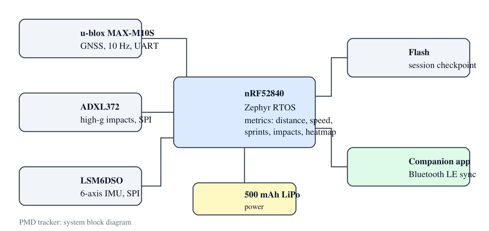
| MCU | nRF52840 (BLE 5) in a Raytac MDBT50Q-1MV2 module, on a custom 4-layer PCB |
| GNSS | u-blox MAX-M10S, 10 Hz |
| High-g accel | ADXL372 |
| IMU | LSM6DSO |
| Battery | 500 mAh LiPo |
The BOM is in hardware/bom.csv.
The board is a 45 x 30 mm, 4-layer PCB designed in KiCad 10: hardware/kicad.
| Layer | Use |
|---|---|
| F.Cu | parts, signals, GND pour |
| In1.Cu | solid GND plane |
| In2.Cu | 3V3 plane |
| B.Cu | signals, GND pour |
Power. USB-C (5.1 kΩ CC pull-downs, so any USB-C charger works) feeds an MCP73831 charger set to about 213 mA (0.4C for the 500 mAh cell). The cell feeds an AP2112K 3.3 V LDO for everything. The GNSS module can draw up to 100 mA at start-up, more than the nRF52840's internal regulator can supply to external parts. A red LED shows charging, and a 1 MΩ / 1 MΩ divider lets firmware read the battery voltage.
RF. The module's antenna sits at the top edge, over the footprint's copper keepout. GNSS uses a passive antenna on a u.FL connector next to the MAX-M10S RF pin. The receiver has its own LNA and SAW filter.
Debug. SWD on a Tag-Connect TC2030-NL footprint, so there's no connector to fit.
| Signal | nRF52840 pin | To |
|---|---|---|
| SPI SCK / MOSI / MISO | P0.13 / P0.15 / P0.17 | ADXL372, LSM6DSO |
| ADXL372 CS / INT1 | P0.20 / P0.24 | U3 |
| LSM6DSO CS / INT1 | P0.22 / P1.09 | U4 |
| UART TX / RX | P0.06 / P0.08 | MAX-M10S RXD / TXD |
| GNSS reset | P0.27 | MAX-M10S RESET_N |
| Battery sense | P0.04 (AIN2) | VBAT / 2 |
| Status LED | P0.31 | D1 |
| USB D+ / D- | module USB pins | USB-C |
Everything is generated from one file, hardware/design.py: parts, nets, placement and track widths. hardware/build.sh then runs the pipeline:
design.py.Current results:
Freerouting gives a different result each run, so build.sh retries routing (up to 5 times) until DRC passes, and fails if it never does. The committed board is a checked run.
Off-board parts (not on the BOM):
Known limits. There's no power switch: the LDO enable is tied to VBAT, and the firmware doesn't yet use System OFF or GNSS standby, so the cell drains between matches. The board hasn't been fabricated, so nothing here is RF-tested or weighed against the 90 g target.
The ADXL372 footprint isn't in the KiCad library. It's drawn from the land pattern in the ADXL372 datasheet (Rev. C, Figure 111).
Fabrication files: hardware/fab/pmd-tracker-gerbers.zip. Design rules are 0.127 mm minimum track and space with 0.6 / 0.3 mm vias, which a standard 4-layer prototype service can make.
All of these are exported straight from the KiCad project by docs/make_images.sh. The board hasn't been fabricated yet, so they're renders and plots, not photos.
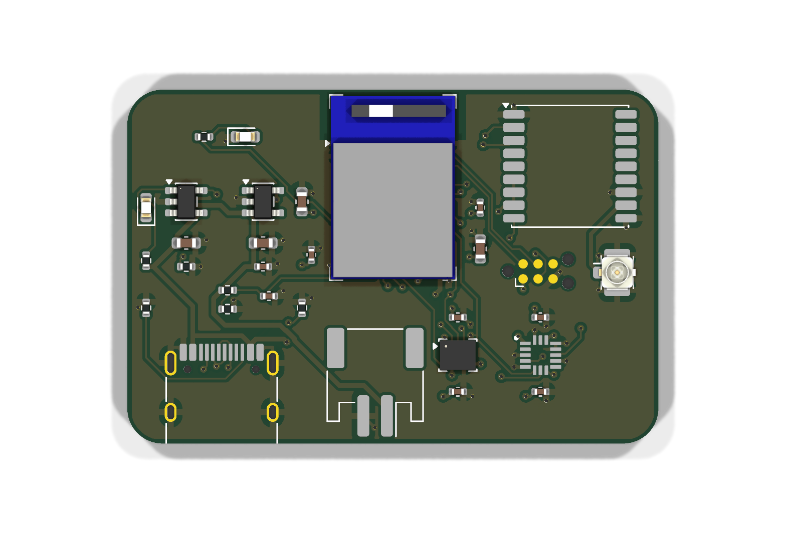 Top render | 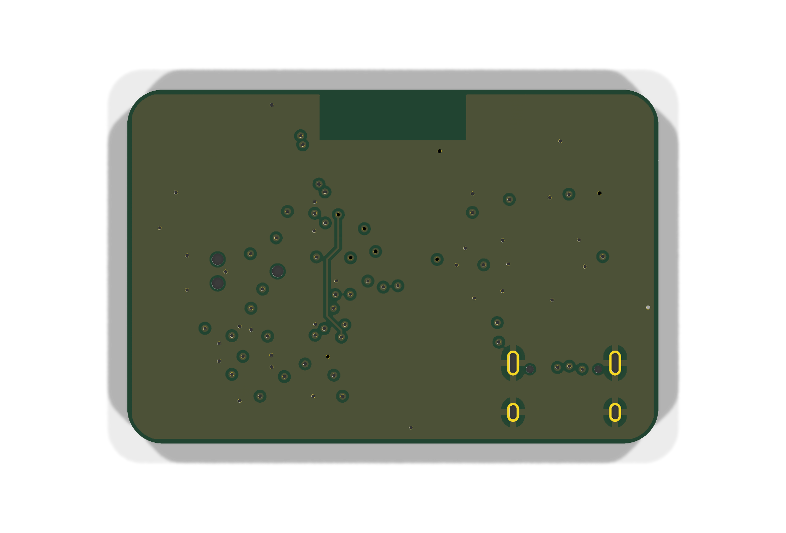 Bottom render |
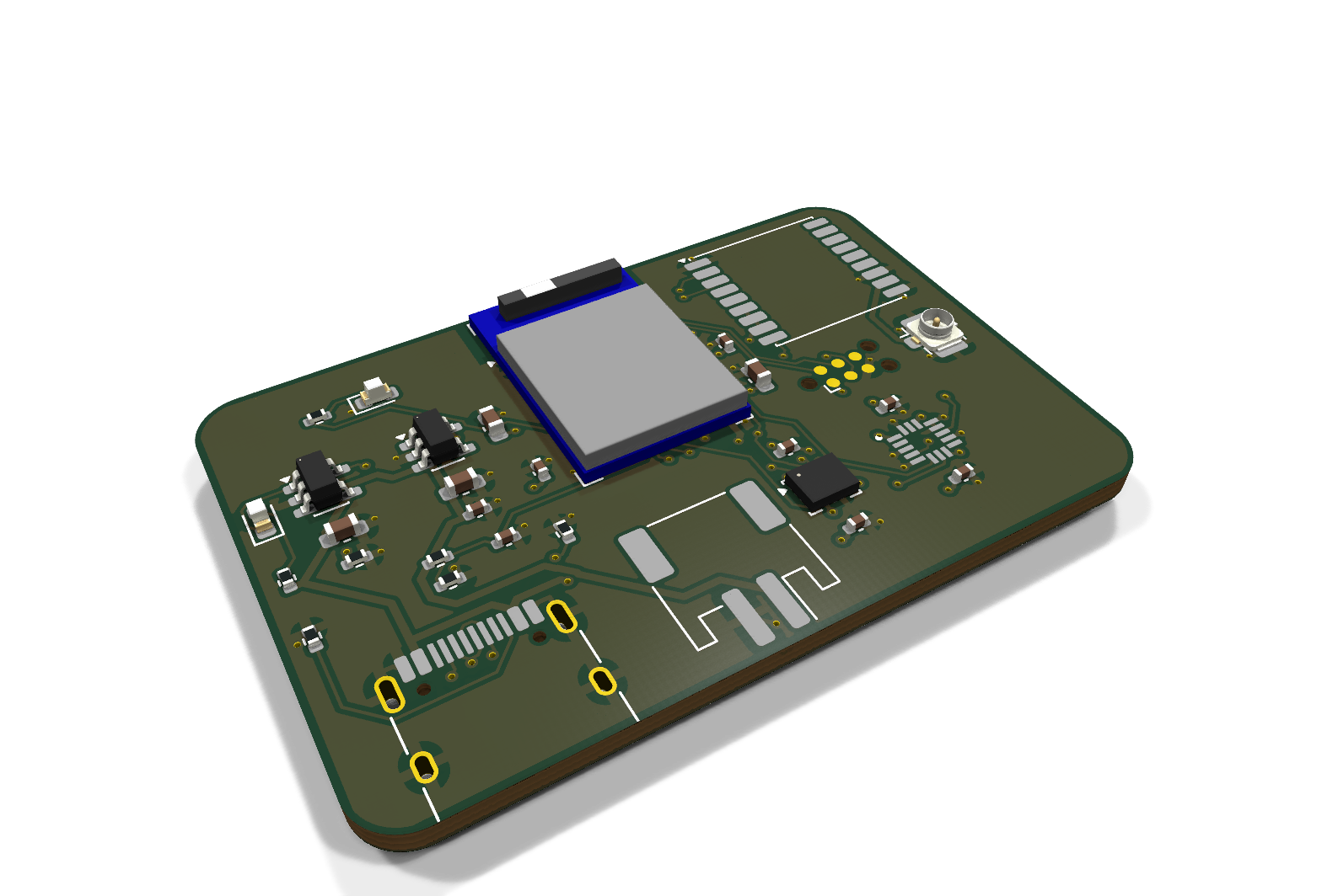 Isometric, front | 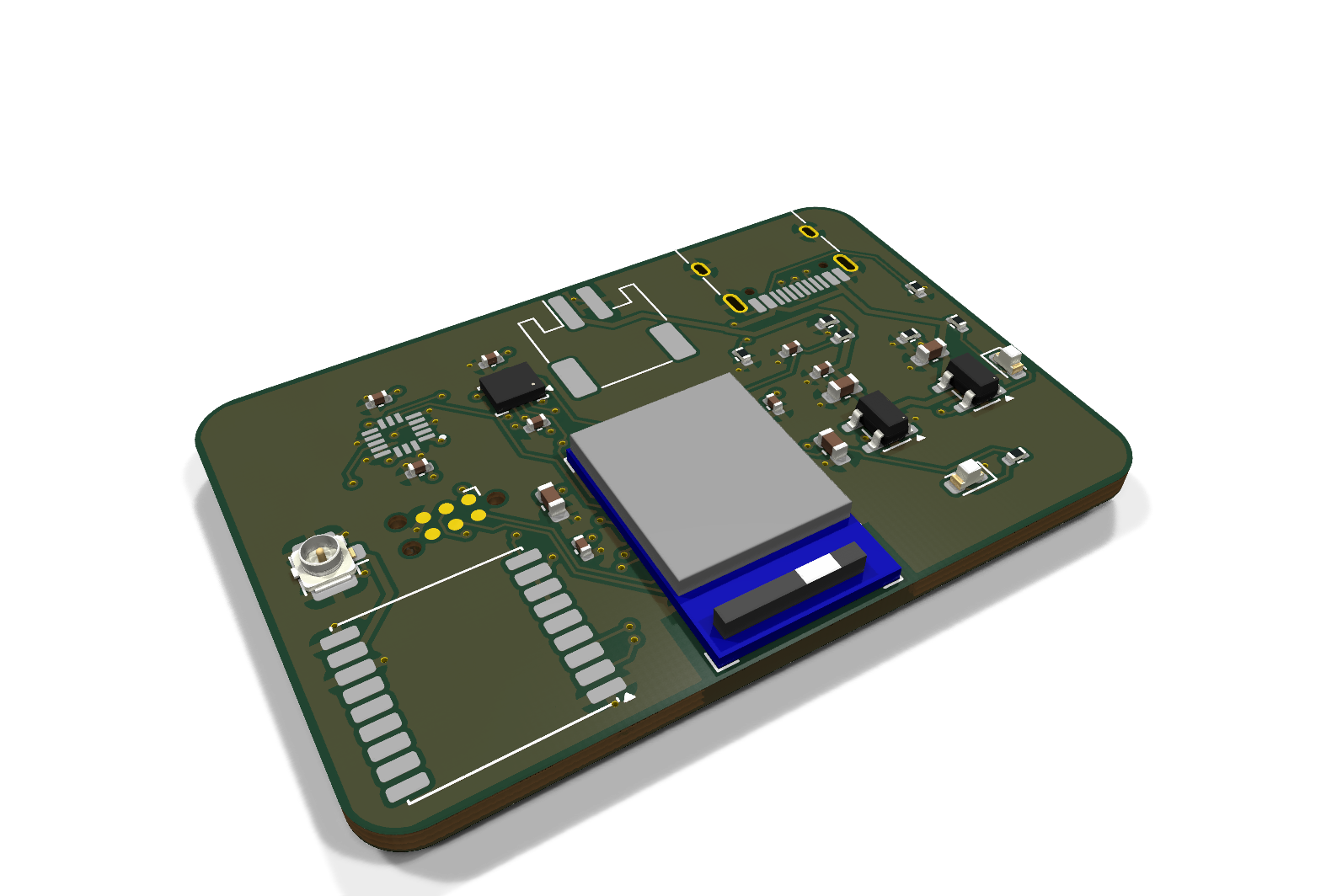 Isometric, back |
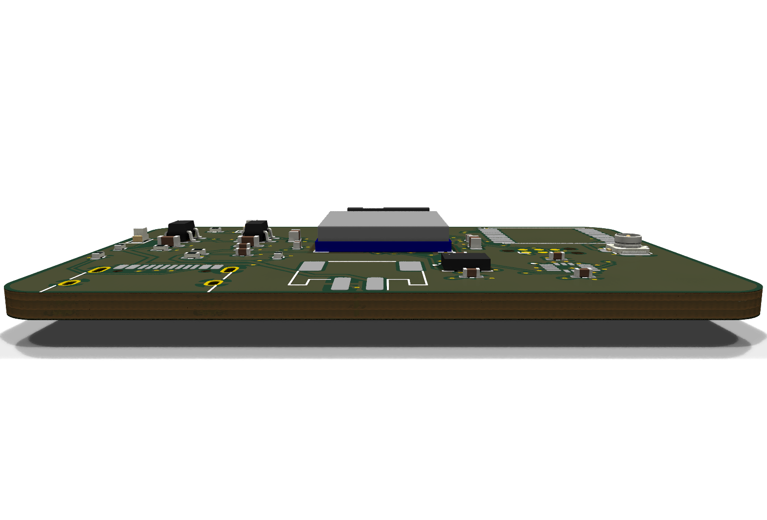 Side profile | 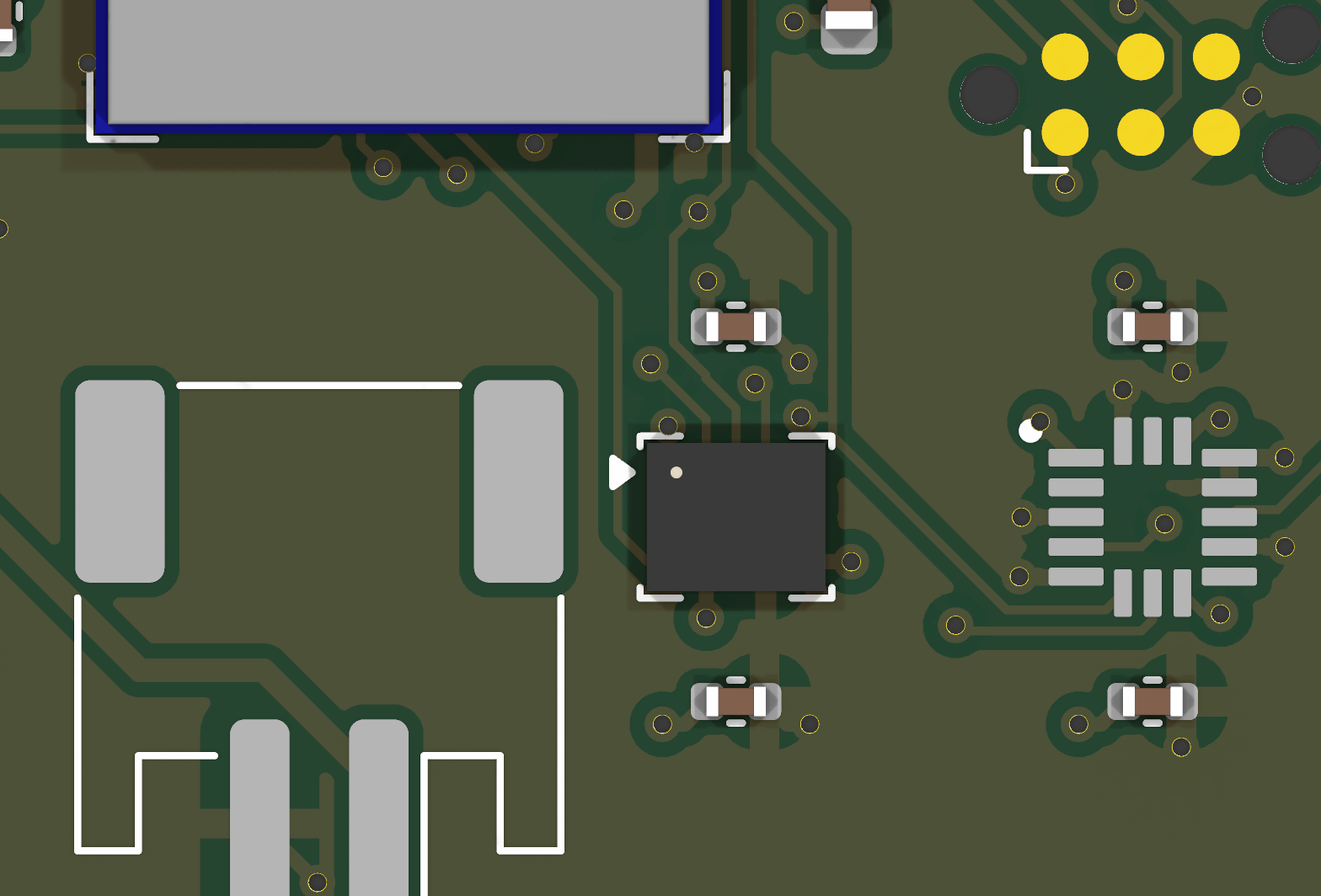 LSM6DSO + ADXL372 close-up |
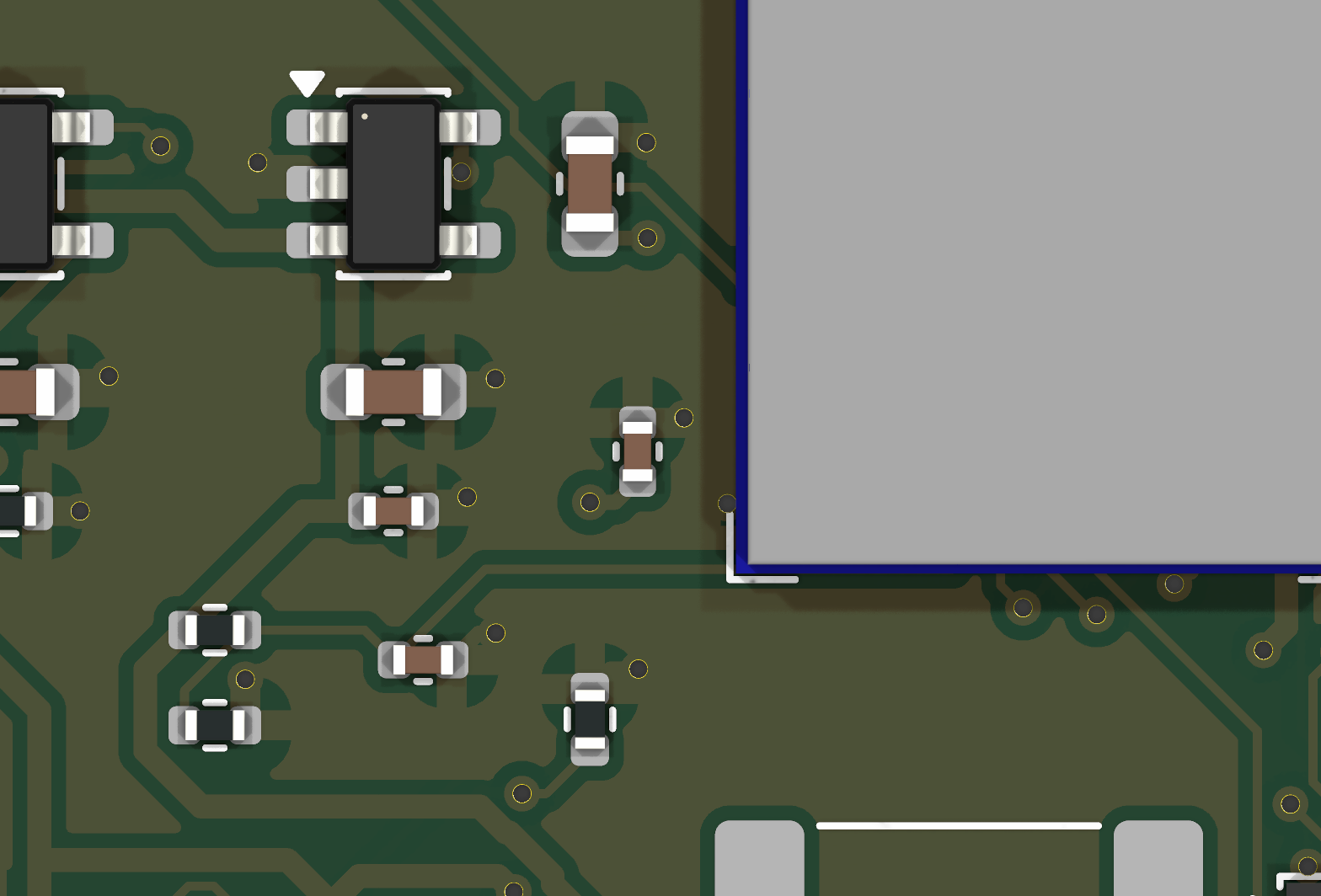 Charger + LDO close-up | 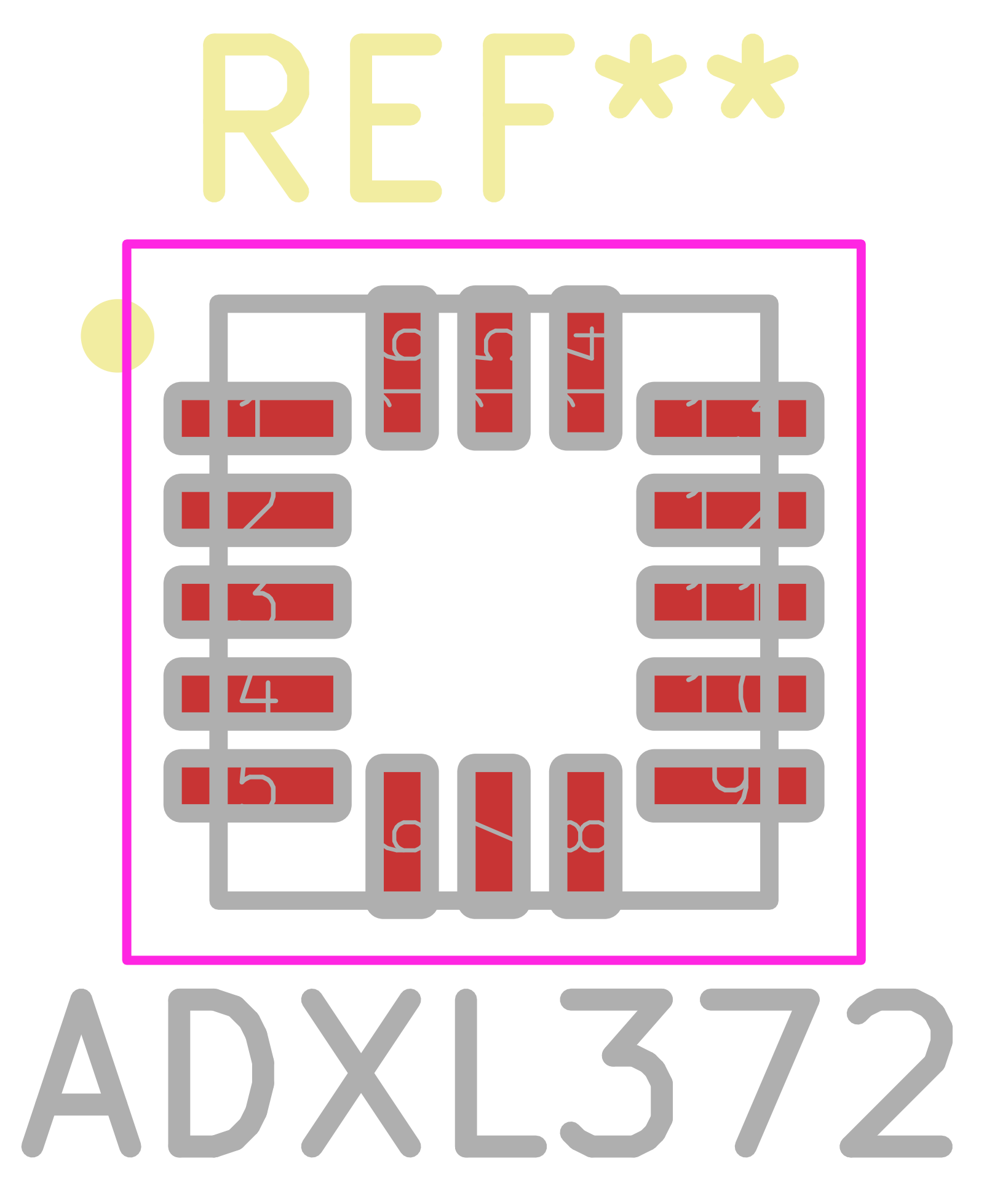 ADXL372 footprint (from datasheet land pattern) |
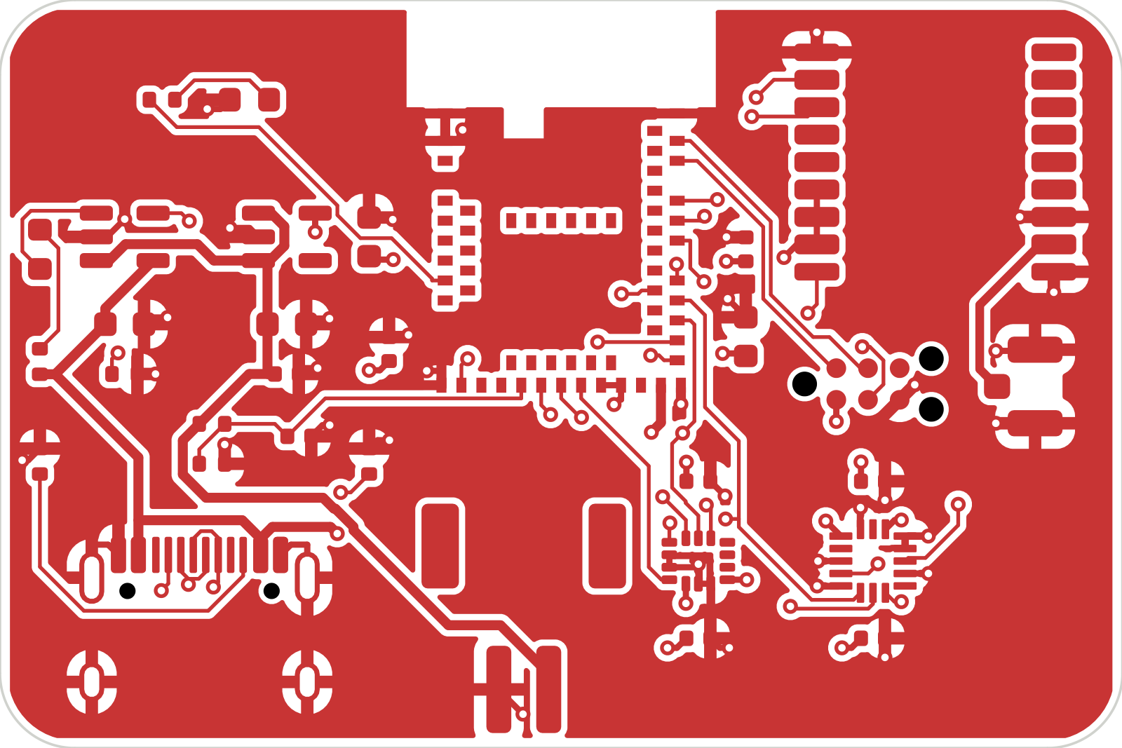 F.Cu (top copper) | 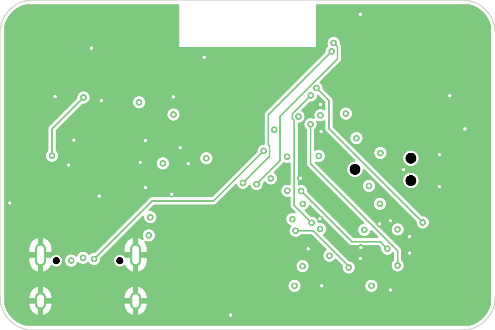 In1.Cu (GND plane) |
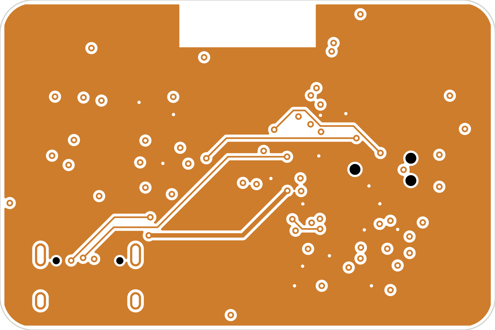 In2.Cu (3V3 plane) | 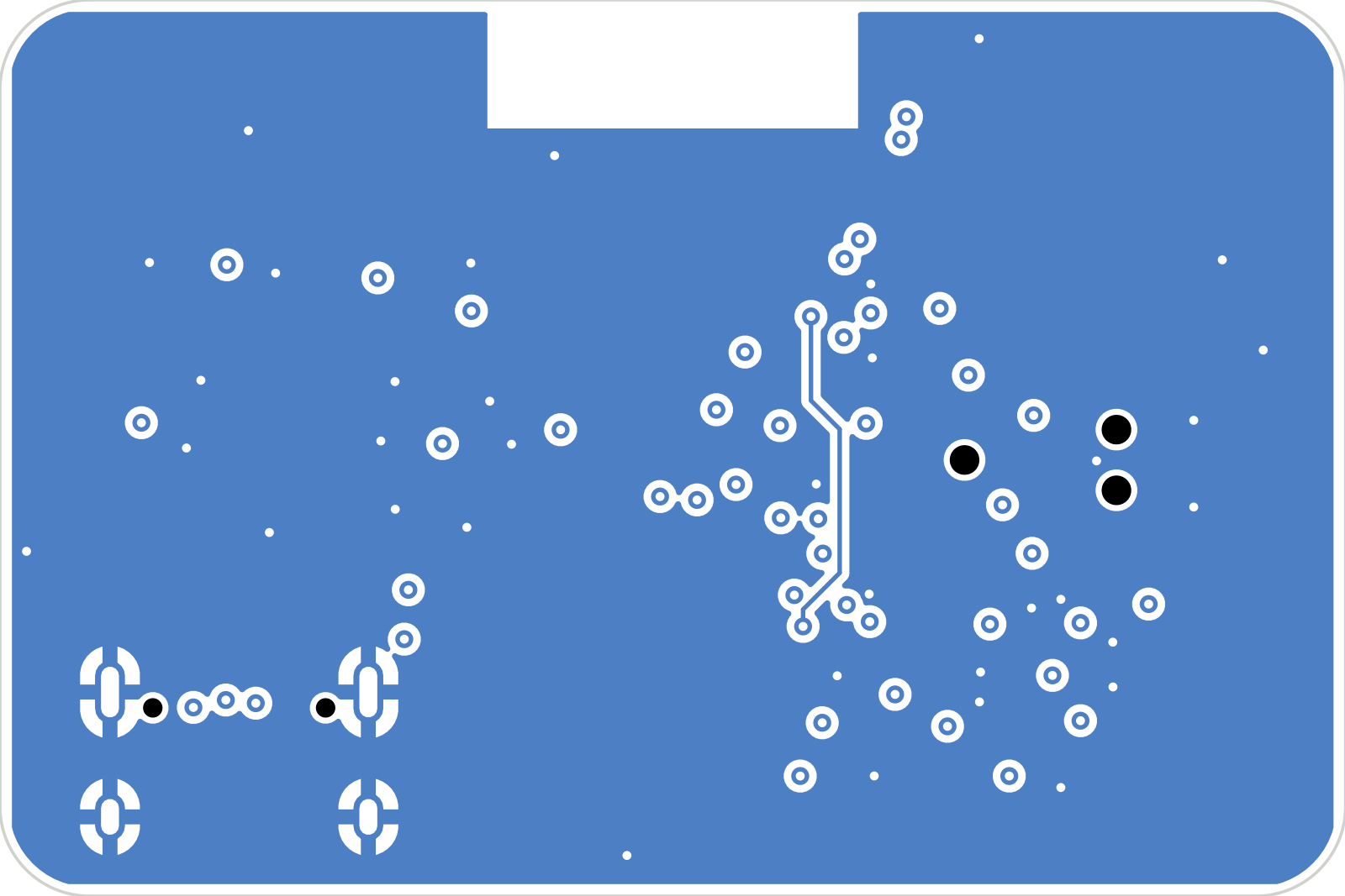 B.Cu (bottom copper) |
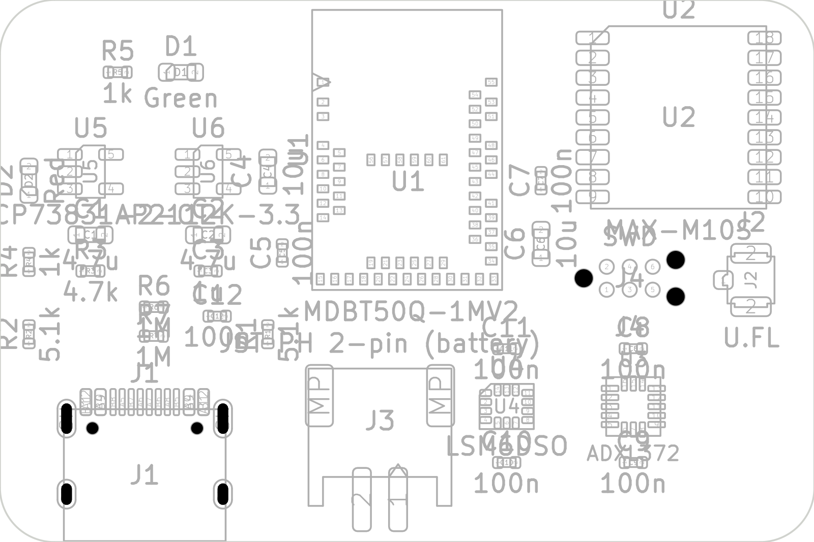 Assembly drawing | Block diagram |
Full schematic: docs/images/08-schematic.png
firmware/
  lib/metrics/     portable C metrics + host self-test
  src/main.c       Zephyr app: sensors, GNSS, flash checkpoint, BLE service
  boards/          devicetree overlay (nRF52840-DK bring-up wiring)
hardware/
  design.py        parts, nets, placement (single source of truth)
  generate.py      writes the KiCad schematic, libraries and PCB
  build.sh         generate -> ERC -> route -> DRC -> fab outputs
  kicad/           KiCad 10 project (.kicad_sch, .kicad_pcb, custom parts)
  fab/             Gerbers + drill, zipped
  bom.csv
docs/
  block-diagram.svg
  board-top.png, board-bottom.png
  images/          15 design images (renders, schematic, layer plots)
make_images.shTest the metrics on a PC. Any C compiler works:
cd firmware/lib/metrics
cc -std=c11 -Wall test_metrics.c metrics.c -lm -o test && ./test
Build the firmware (needs Zephyr 4.x and west). The nRF52840-DK overlay is used for bring-up:
west build -b nrf52840dk/nrf52840 firmware
west flash| Qty | Value | Footprint | References |
|---|---|---|---|
| 7 | 100n | Capacitor_SMD:C_0402_1005Metric | C5, C7, C8, C9, C10, C11, C12 |
| 2 | 10u | Capacitor_SMD:C_0603_1608Metric | C4, C6 |
| 2 | 1M | Resistor_SMD:R_0402_1005Metric | R6, R7 |
| 2 | 1k | Resistor_SMD:R_0402_1005Metric | R4, R5 |
| 2 | 4.7u | Capacitor_SMD:C_0603_1608Metric | C1, C2 |
| 2 | 5.1k | Resistor_SMD:R_0402_1005Metric | R1, R2 |
| 1 | 1u | Capacitor_SMD:C_0402_1005Metric | C3 |
| 1 | 4.7k | Resistor_SMD:R_0402_1005Metric | R3 |
| 1 | ADXL372 | pmd:ADI_LGA-16_3x3.25mm_P0.5mm | U3 |
| 1 | AP2112K-3.3 | Package_TO_SOT_SMD:SOT-23-5 | U6 |
| 1 | Green | LED_SMD:LED_0603_1608Metric | D1 |
| 1 | JST PH 2-pin (battery) | Connector_JST:JST_PH_S2B-PH-SM4-TB_1x02-1MP_P2.00mm_Horizontal | J3 |
| 1 | LSM6DSO | Package_LGA:LGA-14_3x2.5mm_P0.5mm_LayoutBorder3x4y | U4 |
| 1 | MAX-M10S | RF_GPS:ublox_MAX | U2 |
| 1 | MCP73831-2-OT | Package_TO_SOT_SMD:SOT-23-5 | U5 |
| 1 | MDBT50Q-1MV2 | RF_Module:Raytac_MDBT50Q | U1 |
| 1 | Red | LED_SMD:LED_0603_1608Metric | D2 |
| 1 | SWD | Connector:Tag-Connect_TC2030-IDC-NL_2x03_P1.27mm_Vertical | J4 |
| 1 | U.FL | Connector_Coaxial:U.FL_Hirose_U.FL-R-SMT-1_Vertical | J2 |
| 1 | USB-C | Connector_USB:USB_C_Receptacle_HRO_TYPE-C-31-M-12 | J1 |
It measures 45 × 30 mm and has 4 copper layers, 1.6 mm thick.
31 parts, built around the MAX-M10S-00B, MDBT50Q-1MV2, ADXL372BCCZ-RL7 and AP2112K-3.3TRG1. The full list of its parts is on this page, with links to each part's symbol and footprint where PCBKit's library has them.
From the ollielarkins/pmd-tracker repository on GitHub, at the commit this page was made from: the board is hardware/kicad/pmd-tracker.kicad_pcb and its schematic hardware/kicad/pmd-tracker.kicad_sch. PCBKit opens the board in the browser, with nothing to install.
Its repository states no licence, so its author keeps all rights: ask ollielarkins before reusing the design.
nikolaus018/garageDoor-pro
ESP32-C3 + GPS board that opens the garage door when you leave and arrive: firmware, KiCad PCB and perfboard build


joshajohnson/bsidescbr2021
Slides and Design Files for BSides Canberra 2021

jonaschramm/race-tracker
Custom PCB data logger for motorcycle racing: GPS position + IMU motion data, logged to a microSD card, with an e-Paper status display. Built around an ESP32-S3 (WiFi/BT built in) so it can also stream/sync over WiFi.


Vishvak365/OpenCycle
Everything is generated from design.py — do not hand-edit the board and then regenerate, you will lose the edit. If you do route by hand in KiCad, stop using the pipeline for that board and say so in docs/DECISIONS.md.

jgrano/Nx-PCBA
Install all of these before opening the project:
