
2 layers

 techy-robot/CACKLE-Driver-DRV8213_brushed_Motor_Driver
This is a single motor driver based on the DRV8213RTER Texas Instruments chip. It is capable of 4 amps current in a voltage range of 1.65 to 11 volts.
DRV8213 brushed Motor Driver is an open-source printed circuit board by techy-robot, from the techy-robot/CACKLE-Driver-DRV8213_brushed_Motor_Driver repository on GitHub. It is a 4-layer board of 15 × 15 mm with 26 parts on 15 nets, routed with 99 tracks and 61 vias.
It is built around the LP2981-3.3. Its parts include 11 connectors, 10 capacitors, 3 resistors and 2 ICs. It belongs with the robots and motor control boards of this library.
[!TIP] This board is part of a larger modular control board ecosystem, CACKLE
This is a single motor driver based on the DRV8213RTER Texas Instruments chip. It is capable of 4 amps current in a voltage range of 1.65 to 11 volts. This is basically a 2-pin H-bridge driver with integrated protection logic. Driving one pin with PWM will cause the motor to go in one direction, driving both pins will cause braking, and disabling both pins will enable coasting.
The chip has one current sense output, which is tied to both ADC pins A and B on the driver module. Pin C of the ADC pins is tied to FAULT, which is pulled low on triggering. Motor control inputs are on Pins A and B, and the motor output is through a JST PH (2mm Pitch) 2-pin connector which matches the same pin order as the input. The JST-PH connector is 5mm high and is positioned near the center of the board.
The module is a 4-layer PCB with additional exposed traces for the power and ground to add solder for more current carrying capability. I designed it to carry 10 amps with 1 oz outer copper and 0.5oz inner copper, which can be increased to 20 amps current by adding solder. This was the cheapest method to go with, since 2 oz copper would add an additional 30$ per 5 boards.
3D model:
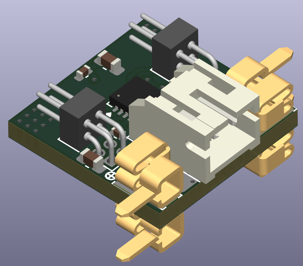
| Qty | Value | Footprint | References |
|---|---|---|---|
| 6 | 10uF, 16v | Capacitor_SMD:C_0603_1608Metric | C1, C2, C3, C4, C5, C7 |
| 4 | Keystone 6100 | custom_Connector:Keystone_6100 | J3, J4, J7, J8 |
| 4 | Keystone 6102 | custom_Connector:Keystone_6102 | J1, J2, J5, J6 |
| 2 | 100nF, 16v | Capacitor_SMD:C_0402_1005Metric | C6, C8 |
| 2 | 10k | Resistor_SMD:R_0402_1005Metric | R1, R3 |
| 2 | Precidip 852-10-004-20-001101 | custom_Connector:Precidip 852-10-004-20-001101 | J10, J11 |
| 1 | 2.2uF, 10v | Capacitor_SMD:C_0402_1005Metric | C9 |
| 1 | 3.3k | Resistor_SMD:R_0402_1005Metric | R2 |
| 1 | 33nF | Capacitor_SMD:C_0603_1608Metric | C10 |
| 1 | DRV8213RTER | Package_DFN_QFN:WQFN-16-1EP_3x3mm_P0.5mm_EP1.68x1.68mm_ThermalVias | U1 |
| 1 | JST PH 2mm horizontal | Connector_JST:JST_PH_S2B-PH-K_1x02_P2.00mm_Horizontal | J9 |
| 1 | LP2981-3.3 | Package_TO_SOT_SMD:SOT-23-5 | U2 |

fedetft/thermal_camera
An open source thermal camera, including firmware, schematic and PCB design.

harmalkar/satellite-prototype
Open-source hardware and software for a satellite with a custom on-board computer to interface over I2C, SPI, and UART with a flash chip, IMU, barometer, camera, and thermal sensors. Built to fit within a 1U form factor.

hackclub/OnBoard
💡 Join 1,000 teenagers and make your first PCB with a $100 grant!

google/mozc-devices
Circuit diagrams and firmware source code for Gboard DIY keyboards

makerforgetech/modular-biped
An open source framework for creating a bipedal modular companion robot.


It measures 15 × 15 mm and has 4 copper layers, 1.6 mm thick.
26 parts, built around the LP2981-3.3. The full list of its parts is on this page, with links to each part's symbol and footprint where PCBKit's library has them.
From the techy-robot/CACKLE-Driver-DRV8213_brushed_Motor_Driver repository on GitHub, at the commit this page was made from: the board is DRV8213 brushed Motor Driver.kicad_pcb and its schematic DRV8213 brushed Motor Driver.kicad_sch. PCBKit opens the board in the browser, with nothing to install.
Its repository states no licence, so its author keeps all rights: ask techy-robot before reusing the design.