2 layers174 × 58 mm
Breakout 112pin Connector
rusefi/rusefi
rusefi - GPL internal combustion engine control unit
42 parts1.2k

 technoiris1/ASTRA-V3
ASTRA-V stand for Autonomous Stabilised Thrust Recovery Ascent Vehicle
ASTRA is an open-source printed circuit board by technoiris1, from the technoiris1/ASTRA-V repository on GitHub. It is a 2-layer board of 66.4 × 77.9 mm with 42 parts on 70 nets, routed with 173 tracks and 26 vias.
It belongs with the RP2040 boards of this library.
heyo! Manan this side - this is my second big hardware project after my foldable 3d printer - ASTRA-V. Stands for Autonomous Stabilised Thrust Recovery Ascent Vehicle.
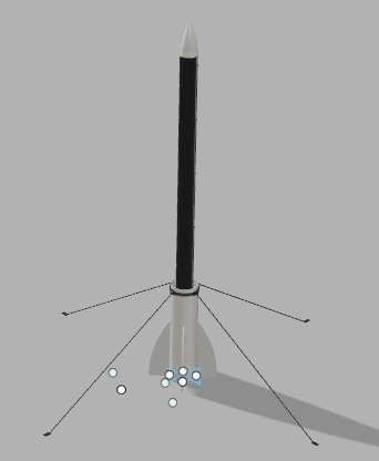
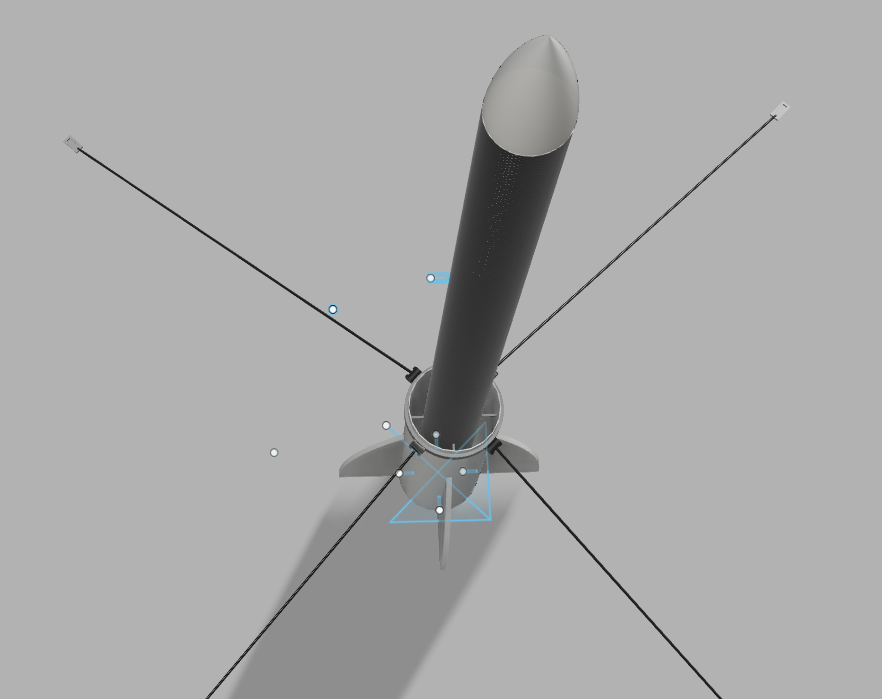 The concept is simple - Go up - attain free fall - thrust again a lil when around 3 feet from the ground - land.
Its using LiDars to calculate the height precisely and they are pretty quick, so no problems.
First iteration - This very iteration of ASTRA-V has the following tasks - going up 15 feet, attaining a proper stable freefall and then land. Now the word land is the main thing, so like this is what the hardest part is - so lets discuss the whole thing step by step.
We are using a RF module to trigger the launch, it is in the flight controller.
The Servo motor will be kicked by the flight controller - which will open the flow of the O2 into the Acrylic Rod Chamber(We will come to the fuel part later on), and along with the servo - an arc ignitor will also be kicked which will burn the fuel. sshhhhhhhhhhiiiiiiiiuuuuuuuuu and with that the burnt fuel gases will come out pressurized of the nozzle and shrrrooooommmm the rockets up - it will go up 30 feet in this iteration.
Pretty simple, once reached the desired height(30 feet here) the valve will be kicked to close. Thus no oxidiser - thus no thrust and no more going up. Then it will just fall down - tearing down the vigilantly through the air.
Now this is the special sauce, the complex thing - in simple words - LiDar sensors are highly sensitive sensors which mainly work on lasers so really quick. They will be sensing the altitude and sending it to the flight computer, now as soon as the altitude or around 15 feet (in this case) is reached - the computer will kick up the servo and ignitor once again to push enough thrust to neutralise the G force attained in the freefall. So like - the whole rocket will have a gentle touchdown in the air using thrusters. Now along with the engine mechanism, one more thing kicked would be the servo motors to deploy the landing legs - they have a really wide span as you can see in the images - so it gonna land really well.
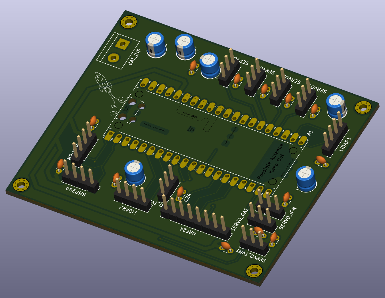
Flight controller is a custom made from scratch which uses Pi pico as the main board. It uses MPU-6050 as the Gyro and BMP-280 as the altimeter as its a barometer. It has pins for breakouts of all these things along with connections with landing servos, LiDar sensors, Fuel Servos and the Arc Ignitor. It has 7 motor connections, 2 LiDar, 1 for MPU6050 and BMP280 each, it has different capacitors placed overall for fluctuations etc.
It is using Acrylic as a fuel along with O2 as the oxidiser. Pretty simple there is a chamber with acrylic rod and a servo controlled apparatus for the input of oxygen into the chamber. So the burnt O2 will heat up and burn the Acrylic rod, thus the Acrylic vapours will move out really really quickly off the nozzle providing thrust.
I am working on a basic servo controlled thrust vectoring system to control the direction of the thrust. This will allow for more precise control of the rocket's trajectory. The servos will be fitted on two different rings, one ring with a servo will be connected to the tube body of rocket and it will rotate another ring inside it, which is housing another servo and that servo will be connected to a ring joint to the rocket motor. So in this way there will be a whole 2-axis thrust vectoring system. I am currently working on the design and 3d model, will put here as soon as i'm done.
cuz am crazy
| Qty | Value | Footprint | References |
|---|---|---|---|
| 14 | 0.1uf | Capacitor_THT:C_Disc_D3.0mm_W1.6mm_P2.50mm | C11, C12, C13, C14, C15, C16, C17, C18, C19, C20, C21, C22, C23, C24 |
| 8 | ~ | Connector_PinHeader_2.54mm:PinHeader_1x03_P2.54mm_Vertical | SERVO1, SERVO2, SERVO3, SERVO4, SERVO5_LGT1, SERVO6_SLN1, SERVO7_TVM1, SERVO8_TVM2 |
| 4 | 100uf | Capacitor_THT:CP_Radial_D6.3mm_P2.50mm | C3, C4, C5, C6 |
| 4 | MountingHole_Pad | MountingHole:MountingHole_2.2mm_M2_Pad_Via | H1, H2, H3, H4 |
| 4 | ~ | Connector_PinHeader_2.54mm:PinHeader_1x04_P2.54mm_Vertical | BMP280_CONN1, LIDAR1, LIDAR2, MPU6050_CONN1 |
| 3 | LOGO | LOGO | G***, G***, G*** |
| 1 | 10uf | Capacitor_THT:CP_Radial_D5.0mm_P2.00mm | C2 |
| 1 | 470uf | Capacitor_THT:CP_Radial_D10.0mm_P5.00mm | C1 |
| 1 | RaspberryPi_Pico | Module:RaspberryPi_Pico_Common_Unspecified | A1 |
| 1 | ~ | Connector_PinHeader_2.54mm:PinHeader_1x08_P2.54mm_Vertical | NRF24_CONN1 |
| 1 | ~ | TerminalBlock:TerminalBlock_bornier-2_P5.08mm | BAT_INP1 |
rusefi/rusefi
rusefi - GPL internal combustion engine control unit


hackclub/sprig
🍃 Learn to code by making games in a JavaScript web-based game editor.

jamro/tiny-engineer
A small desktop robot that brings an AI coding assistant to life, physically acting out when it reads files, thinks, writes code, and finishes work.

hoglet67/RGBtoHDMI
Bare-metal Raspberry Pi project that provides pixel-perfect sampling of Retro Computer RGB/YUV video and conversion to HDMI

hackclub/OnBoard
💡 Join 1,000 teenagers and make your first PCB with a $100 grant!


It measures 66.4 × 77.9 mm and has 2 copper layers, 1.6 mm thick.
42 parts. The full list of its parts is on this page, with links to each part's symbol and footprint where PCBKit's library has them.
From the technoiris1/ASTRA-V repository on GitHub, at the commit this page was made from: the board is FlightController/ASTRA.kicad_pcb and its schematic FlightController/ASTRA.kicad_sch. PCBKit opens the board in the browser, with nothing to install.
Its repository states no licence, so its author keeps all rights: ask technoiris1 before reusing the design.