
2 layers333.4 × 149.9 mm
 TechNickTraff/Pixelmatrix1
Code, PCB and 3D Printing files for the TechNickTräff Pixelmatrix.
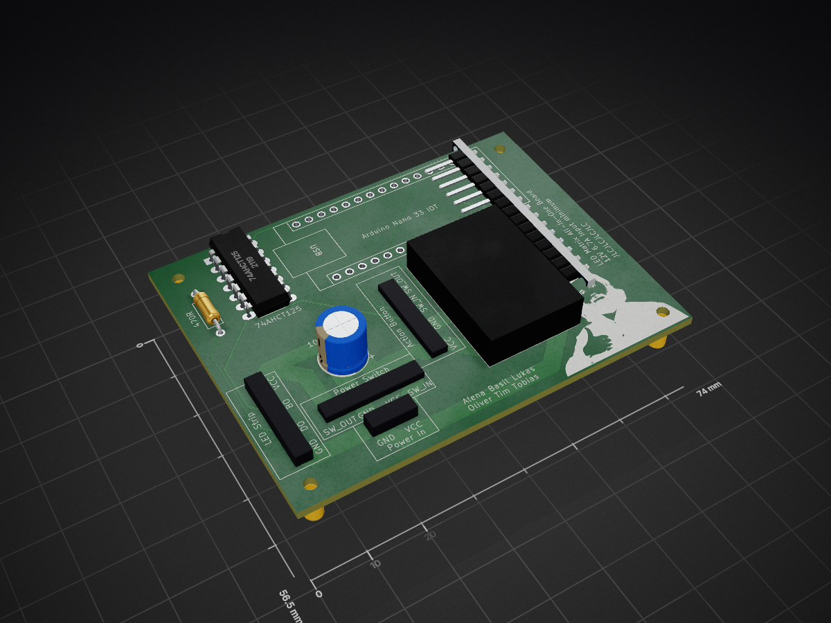
Led matrix is an open-source printed circuit board by TechNickTraff, from the TechNickTraff/Pixelmatrix repository on GitHub. It is a 2-layer board of 74 × 56.5 mm with 14 parts on 35 nets, routed with 69 tracks and 0 vias.
It is built around the 74AHCT125D. Its parts include 2 ICs, 2 connectors, 2 switches, 1 capacitor and 1 resistor. It belongs with the lEDs and displays boards and the AVR (ATmega, ATtiny) boards of this library.
Code, PCB and 3D Printing files for the TechNickTräff Pixelmatrix.
secrets.h.example file to secrets.h and add your WiFi Information.As the Arduino is quite slow it is beneficial to minify the JavaScript.
Install the necessary Build Tools using npm.
Afterwards run npm run build to generate the correct files in the sd Folder.
Either click the Button in the Arduino IDE or use the Arduino CLI command arduino-cli compile.
Using arduino-cli and compiling the project is unfortunately a bit more involved than running arduino-cli compile . in the project directory but very instructive.
Below are some pointers to overcome common issues when using arduino-cli. Additionally, a Makefile is provided to simplify the process.
Installing Dependencies
When managing the project through arduino-cli, the dependencies are not installed automatically. You have to install them manually:
$> arduino-cli lib install SD FastLED WiFiNINA ArduinoJsonMain sketch filename
Compiling the project requires that the main sketch file has the same name as the project directory.
arduino-cli compile --fqbn [..] . will fail if the main sketch file is not named the same as the repository -
that is, if the repository is called Pixelmatrix, the main sketch file should be called Pixelmatrix.ino.User permissions
The flash may initially fail since the user typically does not have write permissions on the serial TTYs by default. This can be fixed by adding the user to the proper group (e.g. dialout, uucp or tty).
sudo chmod 666 /dev/ttyACM0 (or whatever the port is)arduino-cli board list to get the port of the Arduino, e.g. /dev/ttyACM0.ls -l /dev/ttyA* to get the group of the device (uucp in my case).sudo usermod -aG uucp $USER to add yourself to the group.Monitoring the serial output
Using arduino-cli to monitor the serial port, you are typically not fast enough to catch the sketch reporting its IP address.
DEBUG_SERIAL can be defined which delays the setup of the sketch until a serial connection is established.DEBUG_SERIAL macro, run arduino-cli compile --fqbn [..] --build-property build.extra_flags="-DDEBUG_SERIAL" ..Arduino.h is from the Arduino Core Project.
It is automatically installed with the Arduino IDE and can then be added to your CPATH or you can clone the repository and add that to your CPATH (You have to download more files than just Arduino.h).
You have to use a simple web server like php -S, npx serve or other. Whatever you have installed. (Just opening the index.html does not work due to webmodules requiring the same origin policy.)
You can also use the api_endpoint key in the main.mjs file to point the local served web file to your Arduino. Here is an example:
const settings = { api_endpoint: "http://192.168.1.41"};You can reset the Arduino using the button on the back of the Arduino. Pressing it 2 times quickly in sucession will lead to the Arduino halting in the bootloader. (Press the button a third time to exit the boot loader.) Also, here are some reasons how i've crashed my Arduino, it might help.
  while (true)
    ;
Since the Arduino runs a continuous loop, when encountering unrecoverable errors this endless while loop will lead to the watchdog terminating the arduino process. It is the only option (that i know of) to stop executing the programm.
| Qty | Value | Footprint | References |
|---|---|---|---|
| 1 | 12V Power IN | Connector_Wire:SolderWire-0.75sqmm_1x02_P4.8mm_D1.25mm_OD2.3mm | J2 |
| 1 | 16V1000uF | Capacitor_THT:CP_Radial_D8.0mm_P3.50mm | C1 |
| 1 | 470R | Resistor_THT:R_Axial_DIN0207_L6.3mm_D2.5mm_P10.16mm_Horizontal | R1 |
| 1 | 74AHCT125 | Package_DIP:DIP-14_W7.62mm_LongPads | U2 |
| 1 | ACTION_BUTTON | Connector_Wire:SolderWire-0.75sqmm_1x04_P4.8mm_D1.25mm_OD2.3mm | SW2 |
| 1 | Arduino_Nano_33_IOT | Module:Arduino_Nano | A1 |
| 1 | LED_STRIP | Connector_Wire:SolderWire-0.75sqmm_1x04_P4.8mm_D1.25mm_OD2.3mm | J1 |
| 1 | LOGO | LOGO | G*** |
| 1 | POWER_SWITCH | Connector_Wire:SolderWire-0.75sqmm_1x04_P4.8mm_D1.25mm_OD2.3mm | SW1 |
| 1 | ~ | Custom_Footprints:CR-4030L | U1 |
The 10 most common of 14 parts.
It measures 74 × 56.5 mm and has 2 copper layers, 1.6 mm thick.
14 parts, built around the 74AHCT125D. The full list of its parts is on this page, with links to each part's symbol and footprint where PCBKit's library has them.
From the TechNickTraff/Pixelmatrix repository on GitHub, at the commit this page was made from: the board is resources/PCB/KiCad/led_matrix.kicad_pcb and its schematic resources/PCB/KiCad/led_matrix.kicad_sch. PCBKit opens the board in the browser, with nothing to install.
Its repository states no licence, so its author keeps all rights: ask TechNickTraff before reusing the design.


byungyoonc/TrueStrike42
TrueStrike42 is a columnar staggered unibody split keyboard designed to maximize performance and minimize finger fatigue.

twasilczyk/waterdrop-esphome
Waterdrop RO system smart Wi-Fi module for Home Assistant

usedhondacivic/ECE-4760-POV-Display
Persistence of vision display. 30 FPS, full RGB color, and 26" diameter. Updates remotely over WIFI.

GLGPrograms/tinyDiskII
Homemade floppy disk emulator for Apple II series computers

joshjetson/phosphor
A full fledged DAW in TUI and GUI flavors: Run it in the terminal or run it as a desktop app (Desktop App Coming Soon..maybe)