2 layers104.7 × 50.8 mm

 tdwgithub/dih-dah-blue
ESP32C6 Wireless CW paddle project
Paddle is an open-source printed circuit board by tdwgithub, from the tdwgithub/dih-dah-blue repository on GitHub. It is a 2-layer board of 50.8 × 50.8 mm with 16 parts on 19 nets, routed with 75 tracks and 0 vias.
Its parts include 4 connectors, 3 resistors, 2 switches, 1 capacitor and 1 IC. It belongs with the ESP32 and RISC-V boards of this library.
A Bluetooth LE wireless link between a Morse code (CW) paddle and a radio.
Dih Dah Blue replaces the cable between your CW paddle and your radio with a pair of small battery-powered boards. The paddle-side board watches the paddle contacts and sends each transition over Bluetooth LE. The radio-side board drives a solid-state relay wired to the radio's key input. To your radio, it looks like the paddle is plugged straight in.
This repository holds the firmware, KiCad schematics and PCB layouts, and the 3D-printable enclosure described in the Circuit Cellar article "Dih Dah Blue – Bluetooth Remote CW Key" by Todd Wade, W8LEV.
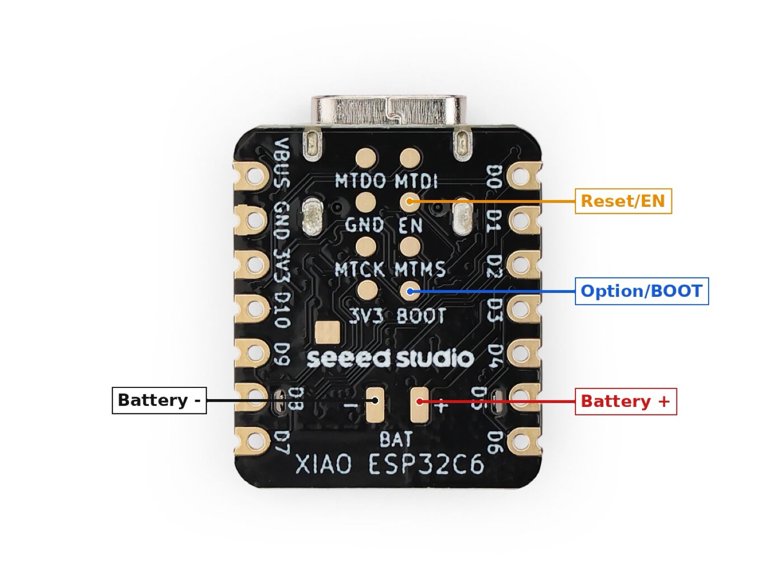
Both boards are built around the Seeed Studio XIAO ESP32-C6. The module provides a RISC-V high-power (HP) core and an ultra-low-power (ULP/LP) core, a built-in LiPo charger and a USB-C port for power and programming.
| Paddle side | Radio side | |
|---|---|---|
| BLE role | Central | Peripheral (advertises as CW_Radio) |
| Connects to | Paddle via 3-position terminal block (left, right, common) | Radio key input via 3-position terminal block, through an ASSR-1228 2-pole solid-state relay |
| Power strategy | ULP core watches the paddle while the HP core sleeps. HP core goes to light sleep after 2 min idle and deep sleep after 10 min | HP core only, light sleep when idle |
| Typical idle current | ~90 µA | ~17 mA |
Paddle side: The ULP core debounces the paddle inputs, places time-stamped events on a queue shared with the HP core, then wakes the HP core. The HP core re-establishes the BLE link if needed and sends each queued event to the radio side. While the link is idle, the HP core steps down from light sleep to deep sleep. A paddle tap wakes everything back up, and the LED blinks three times quickly once the link is up.
Radio side: Accepts the connection, receives paddle events and drives the relay outputs to match.
firmware/
  paddle/     ESP-IDF project: HP core (main/main.c) + ULP core (main/ulp/)
  radio/      ESP-IDF project: radio-side BLE peripheral
hardware/
  paddle/     KiCad project, schematic PDF and BOM for the paddle-side board
  radio/      KiCad project, schematic PDF and BOM for the radio-side board
  panel/      Both boards panelized into one 2-up panel, with ready-to-order Gerbers
enclosure/    OpenSCAD source and STL for the shared enclosure
docs/images/ Photos and rendersEach board is 2" × 2" and uses only through-hole parts. You can also build the circuits on a breadboard or stripboard.
hardware/paddle/Paddle-schematic.pdf and hardware/radio/radio-schematic.pdfhardware/paddle/Paddle-BOM.csv and hardware/radio/radio-BOM.csvhardware/panel/dihdah_blue_r2-gerbers.zip to JLCPCB, PCBWay or a similar board house. It holds both boards on a single panel joined by mouse-bite tabs. Snap them apart and sand the edges.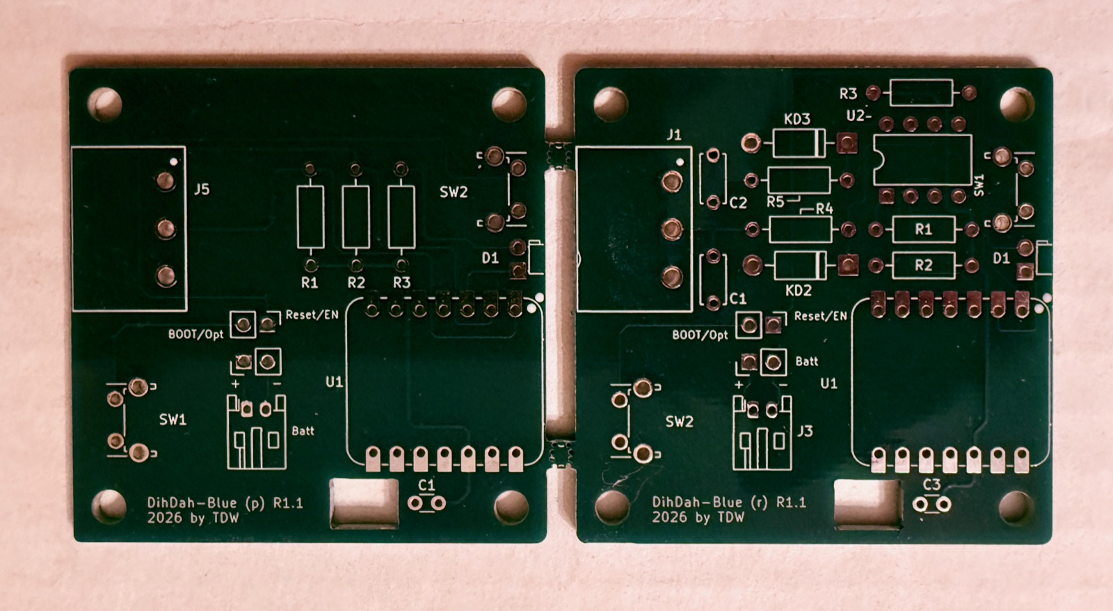
Assembly notes:
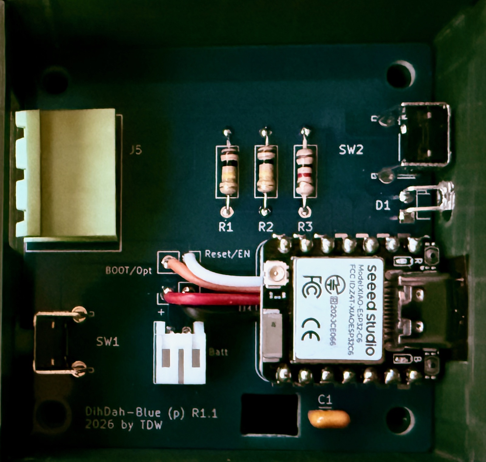
Article correction: The article text says R2 and R3 are the paddle input pull-ups and R1 is the LED resistor. On both boards R3 (1K) is the LED resistor. On the paddle side, R1 and R2 (100K) are the paddle input pull-ups. The schematics (Figures 1 and 2), the PCBs and the files here are correct.
Battery: Either board runs from a single-cell 3.7 V LiPo (the author uses Adafruit's 500 mAh flat pack) or directly from USB-C. Buy batteries from a reputable supplier. A slot in the PCB lets the battery lead pass up from below the board.
Radio-side note: The relay output is meant for "dry contact" key inputs on radios or keyers with a built-in electronic keyer. Don't connect it to older rigs that put a voltage on the key line.
Requires ESP-IDF v5.3.x (developed on v5.3.4).
cd firmware/radio        # or firmware/paddle
idf.py set-target esp32c6
idf.py build
idf.py -p <serial-port> flash monitor
The paddle project builds the ULP program in main/ulp/ and embeds it into the HP-core image automatically.
To force a XIAO into the bootloader, hold BOOT (SW2) while pressing RESET/EN (SW1).
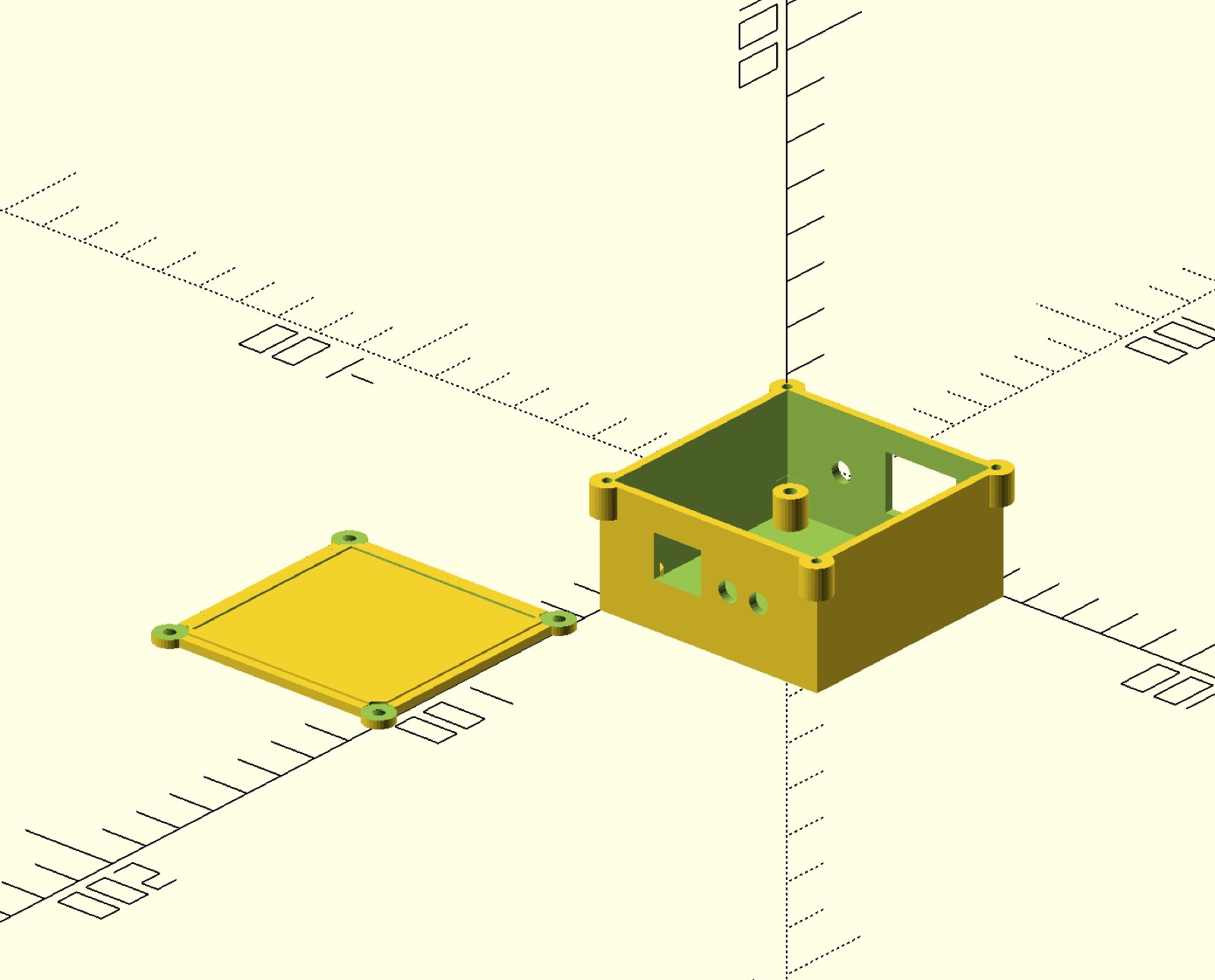
enclosure/dihdah_blue_enclosure.scad is a parametric OpenSCAD design (Listing 1 in the article). It fits either board, and dihdah_blue_enclosure.stl is ready to slice. GitHub shows the STL in a 3D viewer.
firmware/): MIThardware/, enclosure/): CERN-OHL-P-2.0© 2024–2026 Todd D. Wade, W8LEV
| Qty | Value | Footprint | References |
|---|---|---|---|
| 4 | MountingHole | MountingHole:MountingHole_3.5mm | H1, H2, H3, H4 |
| 2 | 100K | Resistor_THT:R_Axial_DIN0207_L6.3mm_D2.5mm_P10.16mm_Horizontal | R1, R2 |
| 2 | Conn_01x02_Pin | Connector_PinHeader_2.54mm:PinHeader_1x02_P2.54mm_Vertical | J1, J4 |
| 2 | SW_Push | Button_Switch_THT:SW_Tactile_SPST_Angled_PTS645Vx83-2LFS | SW1, SW2 |
| 1 | 0.1uF | Capacitor_THT:C_Disc_D3.0mm_W1.6mm_P2.50mm | C1 |
| 1 | 1K | Resistor_THT:R_Axial_DIN0207_L6.3mm_D2.5mm_P10.16mm_Horizontal | R3 |
| 1 | Conn_01x02 | Connector_JST:JST_PH_S2B-PH-K_1x02_P2.00mm_Horizontal | J3 |
| 1 | Screw_Terminal_01x03 | Wurth:691313510003 | J5 |
| 1 | XIAO-ESP32-C6 | Seeed Studio XIAO Series Library:XIAO-ESP32C6-DIP | U1 |
| 1 | ~ | LED_THT:LED_D3.0mm_Horizontal_O1.27mm_Z6.0mm | D1 |
It measures 50.8 × 50.8 mm and has 2 copper layers, 1.6 mm thick.
16 parts. The full list of its parts is on this page, with links to each part's symbol and footprint where PCBKit's library has them.
From the tdwgithub/dih-dah-blue repository on GitHub, at the commit this page was made from: the board is hardware/paddle/Paddle.kicad_pcb and its schematic hardware/paddle/Paddle.kicad_sch. PCBKit opens the board in the browser, with nothing to install.
Its repository states no licence, so its author keeps all rights: ask tdwgithub before reusing the design.


google/mozc-devices
Circuit diagrams and firmware source code for Gboard DIY keyboards

conorpp/u2f-zero
U2F USB token optimized for physical security, affordability, and style

rusefi/rusefi
rusefi - GPL internal combustion engine control unit

VoronDesign/Voron-Hardware
Cool Hardware designed by the Voron Design group

hoglet67/RGBtoHDMI
Bare-metal Raspberry Pi project that provides pixel-perfect sampling of Retro Computer RGB/YUV video and conversion to HDMI

hackclub/OnBoard
💡 Join 1,000 teenagers and make your first PCB with a $100 grant!

