
2 layers74.4 × 51.2 mm
Esp32-wroom timer
AlessandroAU/Chorus32-ESP32LapTimer
This is an ESP32 port of the popular Chorus RF Laptimer
66 parts102GPL-3.0
 TanujRai14/Task_4
In this 5V power supply PCB design, I have implemented a single ground plane approach to ensure minimal noise and better return paths.
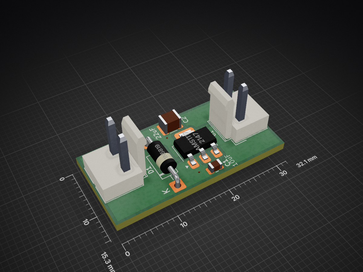
Power Supply is an open-source printed circuit board by TanujRai14, from the TanujRai14/Task_4 repository on GitHub. It is a 2-layer board of 32.1 × 15.3 mm with 6 parts on 3 nets, routed with 37 tracks and 4 vias.
It is built around the AMS1117. Its parts include 2 capacitors, 2 connectors, 1 IC and 1 diode. It belongs with the power boards of this library.
In this 5V power supply PCB design, I have implemented a single ground plane approach to ensure minimal noise and better return paths. All GND connections were routed through a dedicated polygon pour (zone) on the front layer, ensuring low impedance grounding across the board.
To connect ground pins from different locations to the main GND plane, I used vias with 0.7 mm diameter and 0.5 mm drill size, providing solid vertical connections between layers. The track width used throughout the layout is 0.3 mm, which is suitable for the expected current flow of up to 1–1.5 A.
The design successfully passed all Design Rule Checks (DRC), with no errors or unconnected items, confirming the integrity of the routing and electrical connectivity.
| Qty | Value | Footprint | References |
|---|---|---|---|
| 2 | Conn_01x02_Pin | Connector:JWT_A3963_1x02_P3.96mm_Vertical | J1, J2 |
| 1 | 10uF | Capacitor_SMD:C_0805_2012Metric | C1 |
| 1 | 1N5819 | Diode_THT:D_DO-41_SOD81_P10.16mm_Horizontal | D1 |
| 1 | 22uF | Capacitor_SMD:C_1210_3225Metric | C2 |
| 1 | AMS1117 | Package_TO_SOT_SMD:SOT-223-3_TabPin2 | U1 |
AlessandroAU/Chorus32-ESP32LapTimer
This is an ESP32 port of the popular Chorus RF Laptimer


uli/basicengine-pcb
Schematics and PCB layout for the BASIC Engine home computer


MR-DOS/TDR_diploma_thesis
Time domain reflectometer. Includes Hardware, firmware and GUI in Octave. Also a diploma thesis.
It measures 32.1 × 15.3 mm and has 2 copper layers, 1.6 mm thick.
6 parts, built around the AMS1117. The full list of its parts is on this page, with links to each part's symbol and footprint where PCBKit's library has them.
From the TanujRai14/Task_4 repository on GitHub, at the commit this page was made from: the board is Power_Supply.kicad_pcb. PCBKit opens the board in the browser, with nothing to install.
Its repository states no licence, so its author keeps all rights: ask TanujRai14 before reusing the design.