2 layers36 × 58 mm
Ups adaptor
aronreid/ups-to-esp32
Put a USB-only UPS on the network: an ESP32-S3 board and firmware that serves NUT on TCP 3493, with a web UI. No host computer, no Raspberry Pi.
38 parts130GPL-3.0

 TanmayChhatbar/cadence_sensor
WIP
Cadence sensor is an open-source printed circuit board by TanmayChhatbar, from the TanmayChhatbar/cadence_sensor repository on GitHub, published under the GPL-3.0 licence. It is a 2-layer board of 20 × 64.5 mm with 41 parts on 67 nets, routed with 402 tracks and 54 vias.
It is built around the ESP32-S3-WROOM-1-N4, TPD4E05U06DQAR and ICM-42670-P. Its parts include 13 capacitors, 6 resistors, 4 diodes, 3 ICs and 3 connectors. It belongs with the sensors and measurement boards and the ESP32 boards of this library.


This project involves the development of a compact, low-power sensor unit using an ESP32 microcontroller integrated with an accelerometer and powered by a 3.7V LiPo cell, which can be charged using solar energy. The sensor unit wirelessly transmits data over BLE. The system is designed for measuring the cadence when riding a bicycle for live telemetry, with low energy consumption and a tiny form factor.
Hardware Setup
Software Setup
Below is the image of the PCB design, showcasing the layout of the components for the sensor unit.
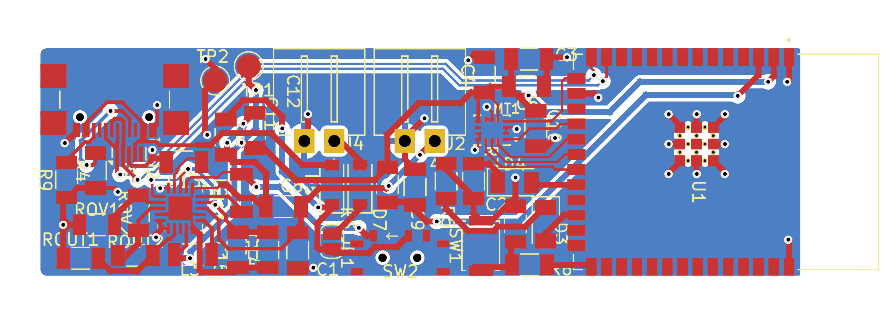
| Qty | Value | Footprint | References |
|---|---|---|---|
| 3 | 0.1uF | Capacitor_SMD:C_1206_3216Metric | C2, C4, C15 |
| 2 | 1uF | Capacitor_SMD:C_1206_3216Metric | C1, C9 |
| 2 | 22uF | Capacitor_SMD:C_1206_3216Metric | C10, C12 |
| 2 | 4.7uF | Capacitor_SMD:C_1206_3216Metric | C11, C14 |
| 2 | 5K1 | Resistor_SMD:R_1206_3216Metric | R4, R9 |
| 2 | 8M2 | Resistor_SMD:R_1206_3216Metric | ROUT2, ROV2 |
| 2 | D_Schottky | Diode_SMD:D_SOD-123 | D5, D7 |
| 1 | .01uF | Capacitor_SMD:C_1206_3216Metric | C13 |
| 1 | 0.01uF | Capacitor_SMD:C_1206_3216Metric | C5 |
| 1 | 100uF | Capacitor_SMD:C_1206_3216Metric | C8 |
| 1 | 10K | Resistor_SMD:R_1206_3216Metric | R6 |
| 1 | 15R | Resistor_SMD:R_1206_3216Metric | R5 |
| 1 | 1K | Resistor_SMD:R_1206_3216Metric | R8 |
| 1 | 2.2uF | Capacitor_SMD:C_1206_3216Metric | C3 |
| 1 | 22uH | Inductor_SMD:L_1206_3216Metric | L2 |
| 1 | 3V3 | TestPoint:TestPoint_Pad_D2.0mm | TP1 |
| 1 | 4.7uH | Inductor_SMD:L_1206_3216Metric | L3 |
| 1 | 4M7 | Resistor_SMD:R_1206_3216Metric | ROUT1 |
| 1 | 5M1 | Resistor_SMD:R_1206_3216Metric | ROV1 |
| 1 | 68R | Resistor_SMD:R_1206_3216Metric | R7 |
| 1 | BQ25570 | Package_DFN_QFN:QFN-20-1EP_3.5x3.5mm_P0.5mm_EP2x2mm | U7 |
| 1 | ESP32-S3-WROOM-1-N4 | ESP32_S3_WROOM_1_N4:XCVR_ESP32-S3-WROOM-1-N4 | U1 |
| 1 | GND | TestPoint:TestPoint_Pad_D2.0mm | TP2 |
| 1 | ICM-42670-P | ICM_42670_P:XDCR_ICM-42670-P | MT1 |
| 1 | JST_BATT | Connector_JST:JST_XH_S2B-XH-A-1_1x02_P2.50mm_Horizontal | J2 |
| 1 | JST_SOL | Connector_JST:JST_XH_S2B-XH-A-1_1x02_P2.50mm_Horizontal | J4 |
| 1 | LED_G | Diode_SMD:D_1206_3216Metric | D3 |
| 1 | LED_R | Diode_SMD:D_1206_3216Metric | D4 |
| 1 | SOL | Jumper:SolderJumper-2_P1.3mm_Open_RoundedPad1.0x1.5mm | JP1 |
| 1 | SW_PWR | switch:switch-MSK-12C02-smd | SW2 |
| 1 | SW_Push | Button_Switch_SMD:SW_Push_SPST_NO_Alps_SKRK | SW1 |
| 1 | TPD4E05U06DQA | Package_SON:USON-10_2.5x1.0mm_P0.5mm | U2 |
| 1 | USB_C_Receptacle_USB2.0_16P | Connector_USB:USB_C_Receptacle_GCT_USB4110 | J1 |
aronreid/ups-to-esp32
Put a USB-only UPS on the network: an ESP32-S3 board and firmware that serves NUT on TCP 3493, with a web UI. No host computer, no Raspberry Pi.

luftaquila/monolith
DIY wireless real-time datalogging platform for Student Formula and Baja.

fl4p/Fugu2
Links: git | kicanvas | cadlab | docs | pdf schematics | IBOM (TODO) | firmware | additional docs & resources

OpenSourceNeuro/Spikeling
A hardware implementation of spiking neurons for neuroscience teaching and outreach

SharKingStudios/Fracture
An infinitely expandable, velocity sensing split midi keyboard.

ademuri/air-filter-controller
The ESP32-S3 uses 3.3V. I want onboard indicator LEDs, and the option to have offboard LEDs as well. Using addressable WS2812-type LEDs is flexible. These need a 5V supply.

besi/split-flap-clock
Split Flap clock or calendar utilising four 28BYJ-48 stepper motors.

gabriele-moretto/dinospand
Agricultural PCB project design and firmware developing.
It measures 20 × 64.5 mm and has 2 copper layers, 1.6 mm thick.
41 parts, built around the ESP32-S3-WROOM-1-N4, TPD4E05U06DQAR and ICM-42670-P. The full list of its parts is on this page, with links to each part's symbol and footprint where PCBKit's library has them.
From the TanmayChhatbar/cadence_sensor repository on GitHub, at the commit this page was made from: the board is KiCAD/cadence sensor.kicad_pcb and its schematic KiCAD/cadence sensor.kicad_sch. PCBKit opens the board in the browser, with nothing to install.
Its repository publishes it under the GPL-3.0 licence: you may reuse it on that licence's terms (keep the author's notice, and for a copyleft licence share your changes alike).