
2 layers327.9 × 139 mm
Coco2
baldengineer/bit-preserve
Project for capturing vintage, classic, aka old computer schematics in KiCad.
147 parts446

 talhazmc/Game-Console1
STM32 based game console PCB design with OLED display, buttons, buzzer, and 555 timer circuit.
Game Console is an open-source printed circuit board by talhazmc, from the talhazmc/Game-Console repository on GitHub. It is a 4-layer board of 105 × 62 mm with 48 parts on 49 nets, routed with 218 tracks and 22 vias.
It is built around the NE555P. Its parts include 12 resistors, 7 capacitors, 7 switches, 5 diodes and 3 ICs. It belongs with the retro computing and games and lEDs and displays boards and the STM32 boards of this library.
STM32 based game console PCB design with OLED display, buttons, buzzer, and 555 timer circuit.
This repository contains my custom STM32-based mini game console PCB project designed with KiCad.
The project was developed as a compact embedded system board that combines an STM32 microcontroller module, OLED display, push buttons, buzzer, LEDs, and a 555 timer circuit on a custom PCB.
The main purpose of this project was to design and build a small game console / gamepad-style embedded system board.
The board includes directional buttons, A/B action buttons, an OLED display for menu and game output, a buzzer for sound feedback, LEDs for visual indicators, and an STM32 module as the main controller.
The PCB was designed in KiCad, manufactured as a custom red PCB, assembled with through-hole and module-based components, and tested as a functional hardware prototype.
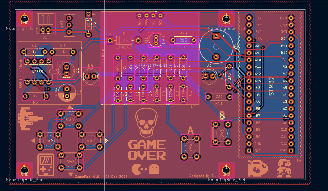
The PCB layout was created in KiCad.
The design includes the STM32 module on the right side, user control buttons on the left and bottom sections, an OLED display area, buzzer, LED indicators, and a separate 555 timer circuit section.
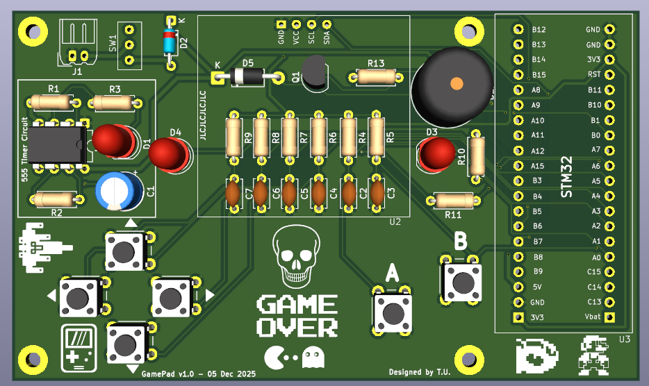
The 3D view was used to check the physical placement of the components before manufacturing.
This step helped verify the button positions, display area, STM32 module placement, buzzer location, mounting holes, and overall board appearance.
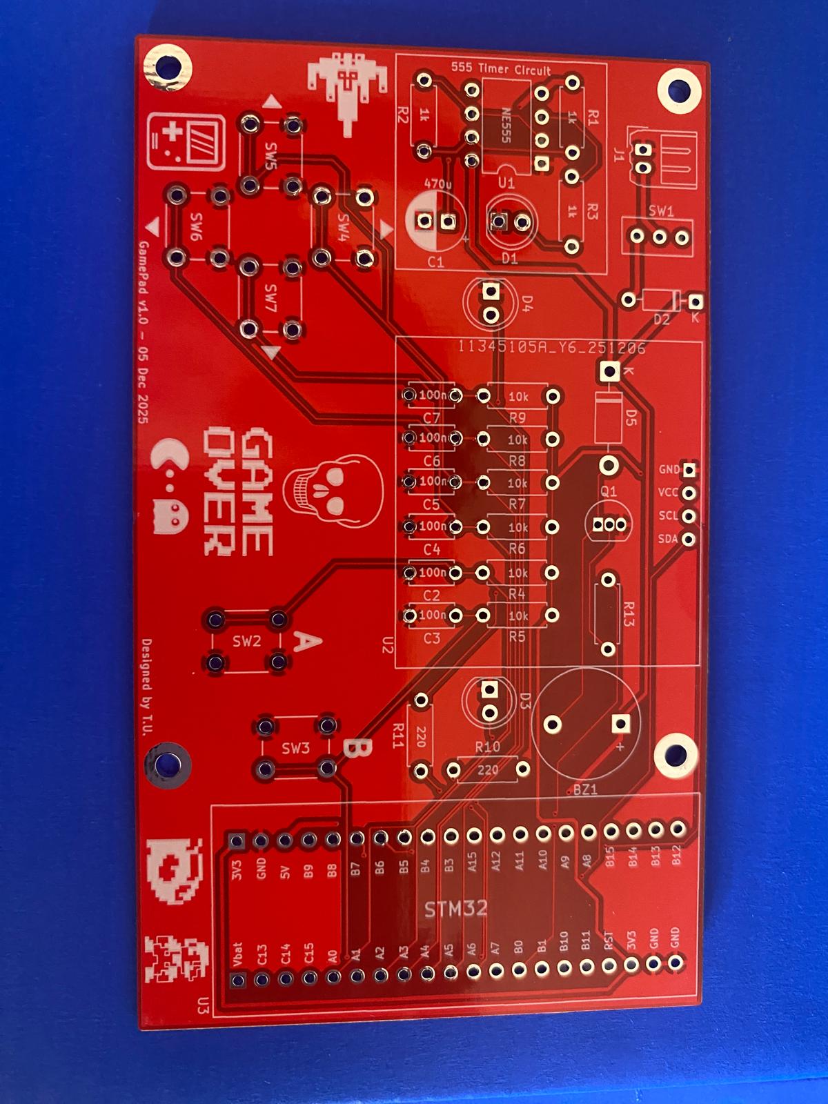
After completing the PCB design, the board was manufactured with a red solder mask.
The silkscreen includes component references, button labels, STM32 pin names, and custom graphics such as the “Game Over” text, skull icon, and pixel-style game icons.
The components were soldered onto the manufactured PCB, including the STM32 module, OLED display, buzzer, LEDs, push buttons, resistors, capacitors, diodes, and 555 timer circuit components.
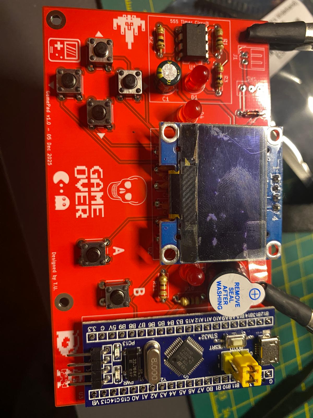
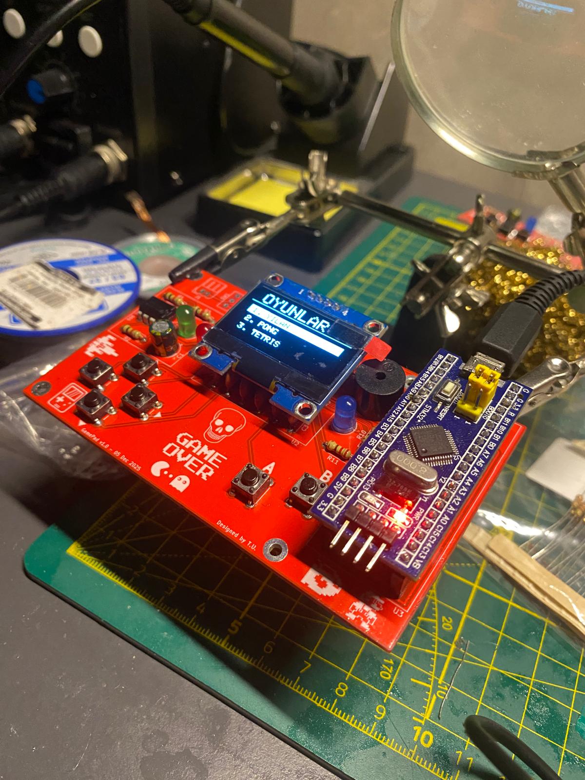
The OLED display was tested with a simple menu interface.
The menu includes different options such as starting the game, Pong mode, and Tetris mode.
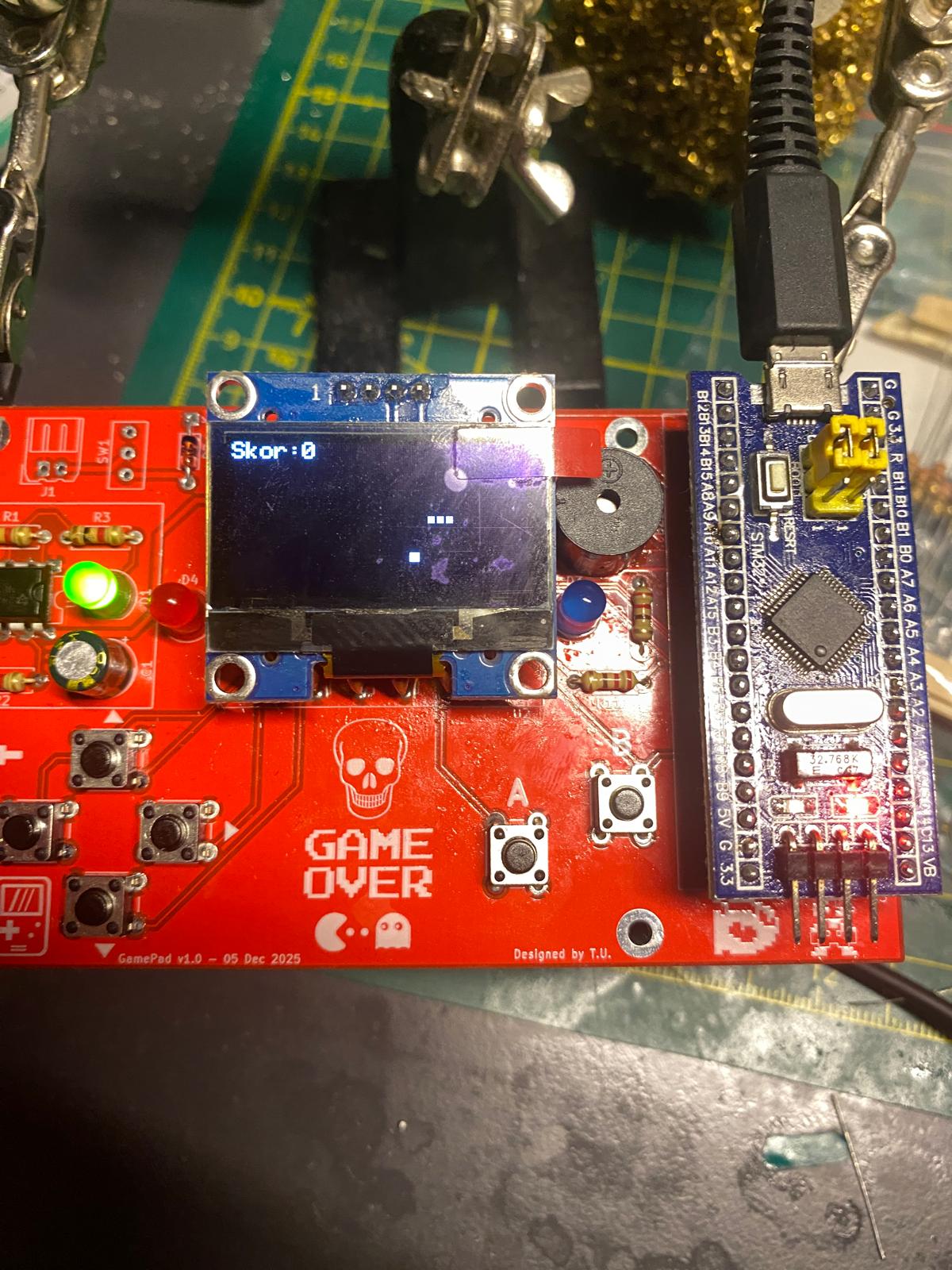
The board was also tested with a basic game screen.
The OLED display shows a score value and simple game objects, while the push buttons are used as user controls.
The STM32 module acts as the main controller of the system.
The push buttons are used as digital inputs for menu navigation and game control. The OLED display provides visual output such as menu options, score, and game graphics.
The buzzer is used for sound feedback, while LEDs provide visual status indication. The 555 timer circuit section was added as an additional timing / signal generation block on the board.
This project demonstrates how a microcontroller, display, buttons, and basic output components can be combined on a custom PCB to create a small interactive embedded system.
Through this project, I gained practical experience in:
Talha Üzümcü
Electrical and Electronics Engineer
GitHub: talhazmc
| Qty | Value | Footprint | References |
|---|---|---|---|
| 7 | LOGO | LOGO | G***, G***, G***, G***, G***, G***, G*** |
| 6 | 100n | Capacitor_THT:C_Disc_D4.7mm_W2.5mm_P5.00mm | C2, C3, C4, C5, C6, C7 |
| 6 | 10k | Resistor_THT:R_Axial_DIN0207_L6.3mm_D2.5mm_P7.62mm_Horizontal | R4, R5, R6, R7, R8, R9 |
| 6 | SW_Push | Button_Switch_THT:SW_PUSH_6mm | SW2, SW3, SW4, SW5, SW6, SW7 |
| 4 | 1k | Resistor_THT:R_Axial_DIN0207_L6.3mm_D2.5mm_P7.62mm_Horizontal | R1, R2, R3, R13 |
| 4 | MountingHole_Pad | MountingHole:MountingHole_2.5mm_Pad | H1, H2, H3, H4 |
| 3 | LED | LED_THT:LED_D5.0mm | D1, D3, D4 |
| 2 | 220 | Resistor_THT:R_Axial_DIN0207_L6.3mm_D2.5mm_P7.62mm_Horizontal | R10, R11 |
| 1 | 1N4007 | Diode_THT:D_DO-41_SOD81_P10.16mm_Horizontal | D5 |
| 1 | 470u | Capacitor_THT:CP_Radial_D6.3mm_P2.50mm | C1 |
| 1 | Buzzer | Buzzer_Beeper:Buzzer_12x9.5RM7.6 | BZ1 |
| 1 | Conn_01x02_Socket | Connector_Molex:Molex_Micro-Latch_53254-0270_1x02_P2.00mm_Horizontal | J1 |
| 1 | D_Schottky | Diode_THT:D_DO-35_SOD27_P7.62mm_Horizontal | D2 |
| 1 | NE555P | Package_DIP:DIP-8_W7.62mm | U1 |
| 1 | NPN | Package_TO_SOT_THT:TO-92_Inline | Q1 |
| 1 | SSD1106 | Globallib:SSD1106_Module | U2 |
| 1 | STM32BluePill | GameConsole:STM32BluePill | U3 |
| 1 | SW_SPDT | GameConsole:Slide_Switch | SW1 |
It measures 105 × 62 mm and has 4 copper layers, 1.6 mm thick.
48 parts, built around the NE555P. The full list of its parts is on this page, with links to each part's symbol and footprint where PCBKit's library has them.
From the talhazmc/Game-Console repository on GitHub, at the commit this page was made from: the board is Game_Console.kicad_pcb and its schematic Game_Console.kicad_sch. PCBKit opens the board in the browser, with nothing to install.
Its repository states no licence, so its author keeps all rights: ask talhazmc before reusing the design.
baldengineer/bit-preserve
Project for capturing vintage, classic, aka old computer schematics in KiCad.

The-Invent0r/8-bit-Computer-PCB
These are the KiCAD files for my 8-Bit Computer.

DarcyJProjects/touchtone555
An open-source DIY, NE555-based analogue synthesizer - play notes with a stylus


benjiaomodular/SynthCard
I designed this project with the help of PCBWay. You can get a copy of these cards through the PCBWay Shared Projects page.

fortinsylvain/MyCpu
Home brew CPU Hardware with 1-bit ALU implementation using 74LSxx, a micro-code and assembler coded in C#.

hackup/C128Diag
Replica of the Commodore C128 Diagnostic Test cartridge Assy No. 325093-01.