2 layers51.5 × 42 mm

 t0mka14/nixie_clock
6 digit nixie clock
Nixie clock is an open-source printed circuit board by t0mka14, from the t0mka14/nixie_clock repository on GitHub. It is a 4-layer board of 191.6 × 128.2 mm with 156 parts on 234 nets, routed with 1,144 tracks and 226 vias.
It is built around the RP2040, DS18B20 and W25Q128JVSIQ, with the HV5530PG-G, DS3231MZ/V+ and ABM8-272-T3 among its other parts. Its parts include 90 resistors, 29 capacitors, 14 ICs, 8 connectors and 4 diodes. It belongs with the lEDs and displays boards and the RP2040 boards of this library.


I got my hands on handful of different nixie tubes when we were moving out some old wardrobes at CTU. I thought this would be just a small project, but well... Anyway it turned out to be a max 6 digit (+2 dividers) USB powered nixie clock. It is controlled by RP2040.
This project contains 4 PCBs (3x 2 layer, 1x 4 layer) in total. They are supposed to be stacked on top of each other using M3 spacers.
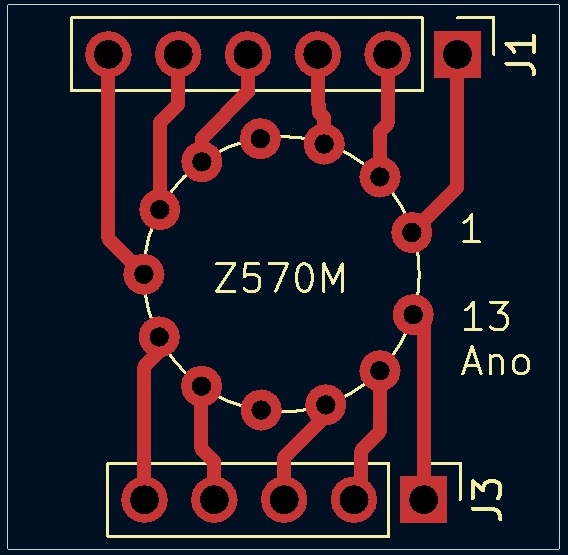
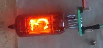
This pcb is just a socket for the Z570M. There were original plastic sockets produced for them, but I don't have one. When soldering the tube, it is better to cool down the contacts near the tube to avoid possible vacuum leak. It can be done with a wet napkin, just be careful to not dissolve the red coating.
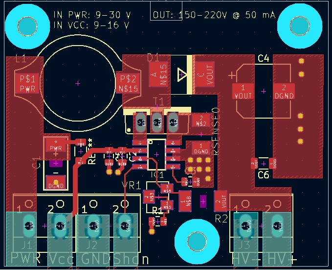
This board is a boost converter powered by MAX1771. The PCB is modified from Nick de Smith design. It generates 150-220V from 12V input for the tubes. Set voltage by trimmer
on the board. It is not galvanically isolated, so be careful to not get shocked.
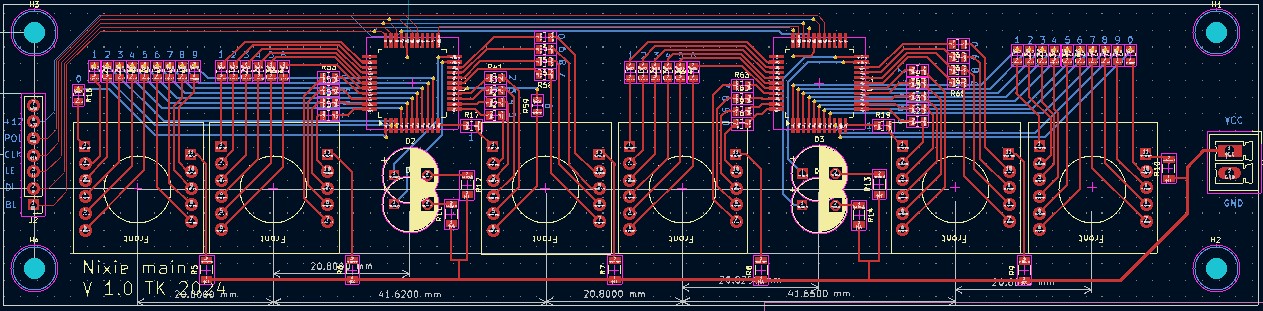
This is basically a holder for the tubes with a HV5530 soldered on.
I personally do not like time multiplexing nixies as it causes more wear on the cathodes. One HV5530 can drive
up to 3 tubes and 2 dividers.
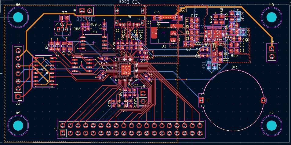
The digital part consists of a RP2040, DS3231 for RTC, and DS18B20 for temperature sensing. The non used pins of RP2040
are fanned out to a standard pin header for additions that will be surely found out just after the design is completed :D
To lower the already high step-up ratio, the TPS2573 requests 12V from USB PD charger. RP2040 is also programmed using
that USB-C. This is the only 4 layer board in the project.
WIP
| Qty | Value | Footprint | References |
|---|---|---|---|
| 68 | R | Resistor_SMD:R_0805_2012Metric | R15, R16, R17, R18, R19, R20, R21, R22, R23, R24, R25, R26, R27, R28, R29, R30 +52 |
| 10 | 100n | Capacitor_SMD:C_0603_1608Metric | C3, C19, C20, C21, C22, C23, C24, C25, C26, C27 |
| 8 | MountingHole | MountingHole:MountingHole_3.2mm_M3 | H1, H2, H3, H4, H5, H6, H7, H8 |
| 6 | 20k | Resistor_SMD:R_1206_3216Metric | R5, R6, R7, R8, R9, R10 |
| 6 | ~ | tomas_lib:Z570M_patice | U5, U6, U7, U8, U9, U10 |
| 5 | 10u | Capacitor_SMD:C_0805_2012Metric | C2, C4, C9, C10, C17 |
| 4 | 5k | Resistor_SMD:R_0805_2012Metric | R1, R2, R3, R4 |
| 4 | D | Capacitor_THT:CP_Radial_D8.0mm_P5.00mm | D1, D2, D3, D4 |
| 4 | R | Resistor_SMD:R_1206_3216Metric | R11, R12, R13, R14 |
| 3 | 10k | Resistor_SMD:R_0805_2012Metric | R83, R84, R85 |
| 3 | 10n | Capacitor_SMD:C_0805_2012Metric | C8, C12, C13 |
| 3 | Conn_01x02_Pin | Connector_PinHeader_2.54mm:PinHeader_1x02_P2.54mm_Vertical | J5, J8, J9 |
| 2 | 15p | Capacitor_SMD:C_0603_1608Metric | C29, C30 |
| 2 | 1k | Resistor_SMD:R_0603_1608Metric | R89, R90 |
| 2 | 1u | Capacitor_SMD:C_0603_1608Metric | C18, C28 |
| 2 | 22u | Capacitor_SMD:C_0805_2012Metric | C15, C16 |
| 2 | 27.4 | Resistor_SMD:R_0603_1608Metric | R86, R87 |
| 2 | 330p | Capacitor_SMD:C_0603_1608Metric | C5, C6 |
| 2 | 4.7u | Capacitor_SMD:C_0805_2012Metric | C7, C11 |
| 2 | Conn_01x07_Pin | Connector_PinHeader_2.54mm:PinHeader_1x07_P2.54mm_Vertical | J2, J3 |
| 2 | HV5530 | tomas_lib:PQFP-44_HV5530 | U11, U12 |
| 1 | 10k | Resistor_SMD:R_0603_1608Metric | R88 |
| 1 | 1u | Capacitor_SMD:C_0805_2012Metric | C1 |
| 1 | 4504 | tomas_lib:Texas_PDSO_G16 | U4 |
| 1 | ABM8-272-T3 | nixie_lib:ABM8-272-T3 | Y2 |
| 1 | Battery_Cell | Battery:Battery_Panasonic_CR2032-HFN_Horizontal_CircularHoles | BT1 |
| 1 | Conn_01x02_Pin | Connector_Phoenix_MC:PhoenixContact_MCV_1,5_2-G-3.5_1x02_P3.50mm_Vertical | J4 |
| 1 | Conn_02x19_Odd_Even | Connector_PinHeader_2.54mm:PinHeader_2x19_P2.54mm_Vertical | J1 |
| 1 | DS18B20 | Package_TO_SOT_THT:TO-92_Inline | U2 |
| 1 | DS3231MZ | Package_SO:SOIC-8_3.9x4.9mm_P1.27mm | U1 |
| 1 | NCP1117-3.3_SOT223 | Package_TO_SOT_SMD:SOT-223-3_TabPin2 | U3 |
| 1 | RP2040 | Package_DFN_QFN:QFN-56-1EP_7x7mm_P0.4mm_EP3.2x3.2mm | U15 |
| 1 | USB_C_Receptacle_USB2.0_16P | tomas_lib:Conn_USB_C_Socket_Molex_2171790001 | J6 |
| 1 | W25Q128JVS | Package_SO:SOIC-8_5.3x5.3mm_P1.27mm | U13 |
| 1 | ~ | tomas_lib:IC_TPS25730D | TPS25730D1 |


dm2lct/Nixieclock_kit
This is a Nixie-clock controlled by a ESP8266 module with NTP and MQTT support.


dm2lct/tlnixie
PCB files for the Turmlabor nixie clock 2.0


Fredovsky/B13B-Nixie-clock
Nixie clock made from F9057 Nixie tubes (B13B sockets).


ikajdan/katia
A split keyboard with 6 by 3 column staggered keys and 3 thumb keys, based on the Crkbrd design

alvarop/swd2usbc
Have you ever wanted to debug your device over USB-C? Sometimes there's not enough room for a JTAG/SWD connector, or even Tag-Connect pads!
It measures 191.6 × 128.2 mm and has 4 copper layers, 1.6 mm thick.
156 parts, built around the RP2040, DS18B20, W25Q128JVSIQ and HV5530PG-G. The full list of its parts is on this page, with links to each part's symbol and footprint where PCBKit's library has them.
From the t0mka14/nixie_clock repository on GitHub, at the commit this page was made from: the board is nixie_clock/nixie_clock.kicad_pcb and its schematic Z570M_socket/Z570M_socket.kicad_sch. PCBKit opens the board in the browser, with nothing to install.
Its repository states no licence, so its author keeps all rights: ask t0mka14 before reusing the design.