Skip to the content
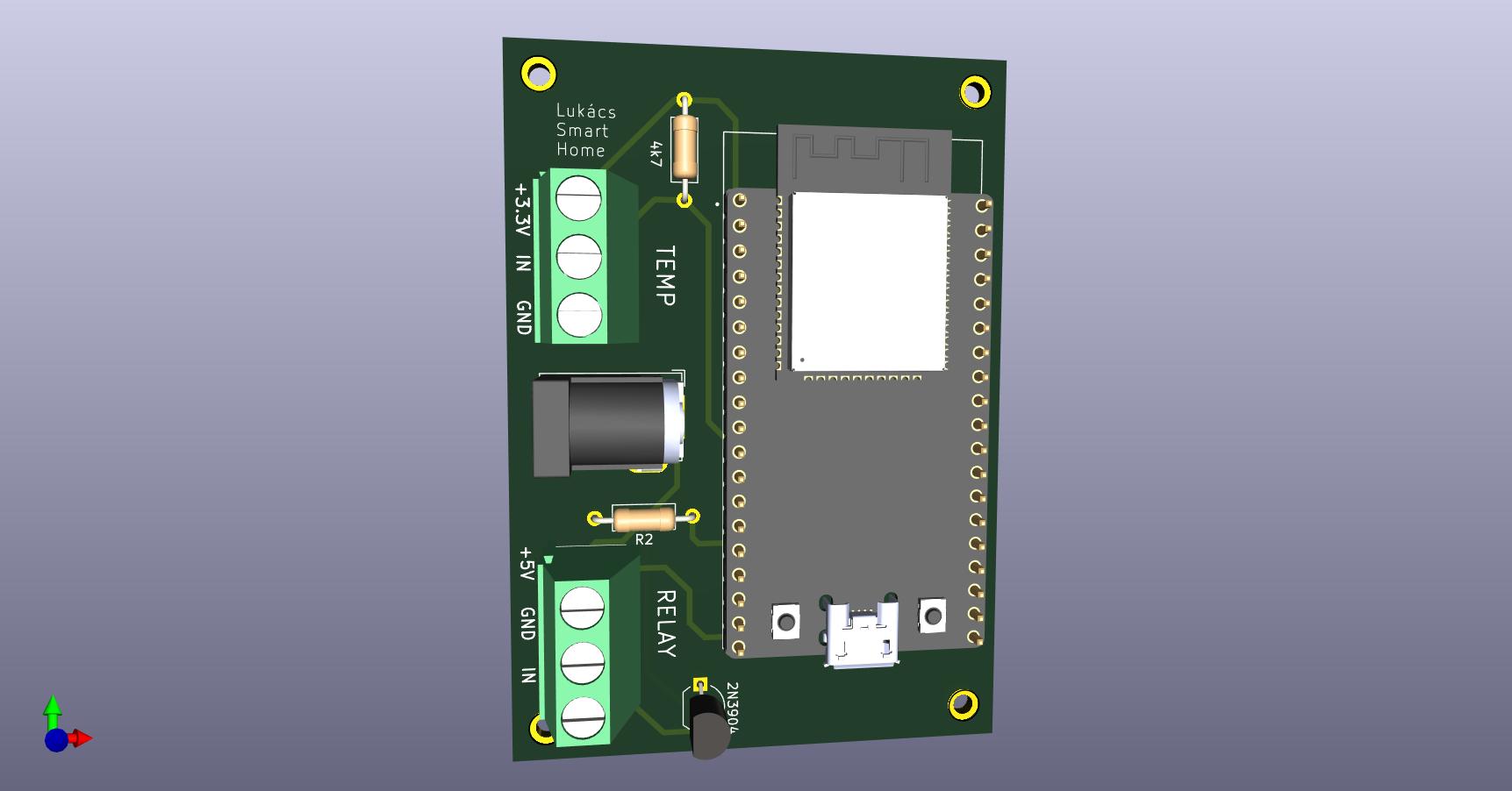
2 layers52.5 × 74 mmEsp32 devkit, the printed circuit board in 3D

SmartHome Relay is an IoT project using an ESP32 to remotely control a relay and monitor boiler temperature via the Blynk platform. 🌡️📱Features include real-time temperature monitoring, thermostat automation, and notification toggles. Includes custom PCB design (KiCAD) and Arduino IDE code.

Size
52.5 × 74 mm
Copper layers
2
Thickness
1.6 mm
Parts
11
Nets
39
Pads
58
Tracks, vias
31, 0
Routed
Yes
KiCad
KiCad 8.0 (file 20240108)
Created
19 Nov 2024
Updated
19 Nov 2024

Overview

Esp32 devkit is an open-source printed circuit board by szabilukacs, from the szabilukacs/SmartHomeRelay repository on GitHub. It is a 2-layer board of 52.5 × 74 mm with 11 parts on 39 nets, routed with 31 tracks and 0 vias.

Its parts include 3 connectors, 2 resistors, 1 IC and 1 transistor. It belongs with the home automation and IoT boards and the ESP32 boards of this library.

README

README.md

SmartHome Relay 🌡️🔔

This project is a smart boiler control and monitoring system built on the Blynk platform. Using an ESP32, this system allows users to:

  • Remotely control a relay to activate or deactivate the built-in heating resistance of the boiler.
  • Monitor the temperature inside the boiler in real-time.
  • Automate boiler heating using thermostat-like behavior based on a set temperature range.
  • Enable or disable notifications for temperature changes or system events.

The project combines hardware design, embedded programming, and IoT integration for a seamless smart home experience.


📜 Table of Contents

Features ✨

  • Remote Control: Control the heating resistance via the Blynk mobile app.
  • Real-time Temperature Monitoring: Display temperature data from the boiler directly in the app.
  • Automated Thermostat Mode: Set a target temperature range, and the system will automatically control the relay.
  • Notification Toggle: Enable or disable notifications for system status and alerts.
  • Custom PCB Design: Compact and efficient PCB for the ESP32 and relay circuit, designed in KiCAD.
  • User-friendly Interface: Intuitive and easy-to-use Blynk app interface for controlling and monitoring.

Getting Started

Hardware

  • Microcontroller: ESP32
  • Temperature Sensor: DS18B20
  • Relay Module: Controls the heating resistance
  • Custom PCB: Designed to integrate the ESP32, relay, and sensor connections

Software

  • Arduino IDE: Development environment for the ESP32 firmware
  • Blynk: Cloud-based platform for IoT app creation
  • KiCAD: Used for designing the PCB

Hardware Design📐

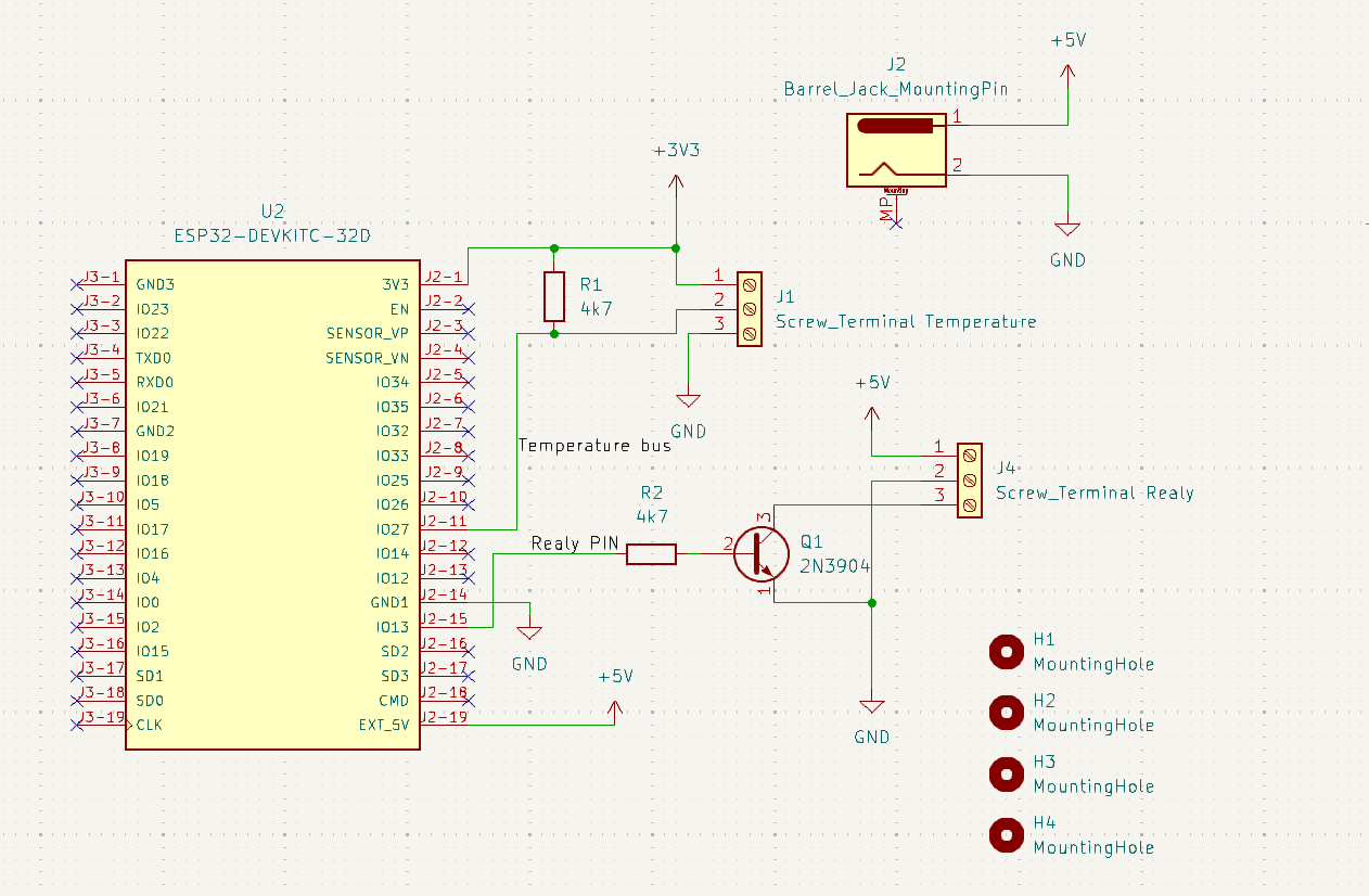
Circuit Diagram

Circuit Diagram

PCB 3D View

PCB 3D View


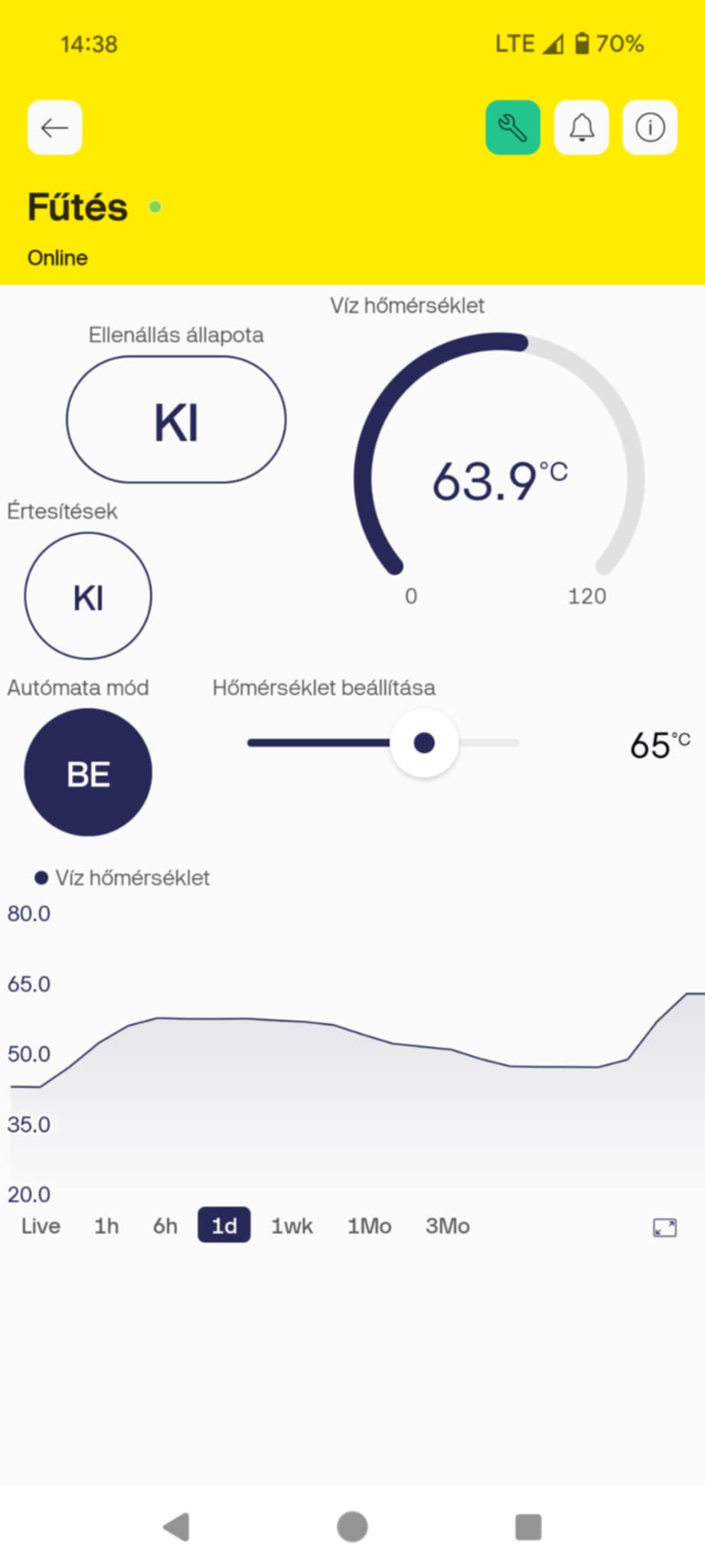
Blynk App Interface 📱

The Blynk app provides an intuitive interface for interacting with the SmartHome Relay system:

Blynk UI

Features:

  • Relay Control: Toggle the relay to activate or deactivate the heating resistance.
  • Temperature Display: Real-time temperature monitoring from the boiler.
  • Automation Mode: Set a target temperature range for thermostat-like operation.
  • Notifications Toggle: Enable or disable notifications for system status and alerts.

Code Overview

Dependencies

Ensure the following libraries are installed in Arduino IDE:

  1. Blynk
  2. ESP32 Board Support
  3. Temperature Sensor Library

Uploading the Code

  1. Clone the repository.
  2. Open the .ino file in Arduino IDE.
  3. Configure your WiFi and Blynk credentials in the code.
  4. Upload the code to the ESP32 using a USB connection.

PCB Design

  • The PCB design was created using KiCAD.
  • It includes the ESP32, relay, and connectors for the temperature sensor.
  • You can [link PCB ordering instructions here] if relevant.

Parts

11
QtyValueFootprintReferences
4MountingHoleMountingHole:MountingHole_2.2mm_M2_ISO7380_PadH1, H2, H3, H4
24k7Resistor_THT:R_Axial_DIN0207_L6.3mm_D2.5mm_P10.16mm_HorizontalR1, R2
2Screw_Terminal_01x03TerminalBlock:TerminalBlock_bornier-3_P5.08mmJ1, J4
12N3904Package_TO_SOT_THT:TO-92_Inline_WideQ1
1Barrel_Jack_MountingPinConnector_BarrelJack:BarrelJack_GCT_DCJ200-10-A_HorizontalJ2
1ESP32-DEVKITC-32DSzabi_footprints:MODULE_ESP32-DEVKITC-32DU2

Similar boards

  • 2 layers60 × 30 mmController, the printed circuit board in 3D

    Controller

    google/mozc-devices

    Circuit diagrams and firmware source code for Gboard DIY keyboards

    11 parts3kApache-2.0
  • 2 layers103 × 30.5 mmTS Front Endcap, the printed circuit board in 3D

    TS Front Endcap

    EEVengers/ThunderScope

    ThunderScope GitHub Repo

    11 parts1.3kMIT
  • 2 layers26 × 30 mmExpansion Card, the printed circuit board in 3D

    Expansion Card

    FrameworkComputer/ExpansionCards

    Reference designs and documentation to create Expansion Cards for the Framework Laptop

    11 parts1.1kCC-BY-4.0
  • 2 layers53.9 × 23.2 mmBuffer, the printed circuit board in 3D

    Buffer

    hoglet67/RGBtoHDMI

    Bare-metal Raspberry Pi project that provides pixel-perfect sampling of Retro Computer RGB/YUV video and conversion to HDMI

    11 parts1kGPL-3.0
  • 2 layers10 × 20 mm2 connector Sensor Board, the printed circuit board in 3D

    2 connector Sensor Board

    hackclub/OnBoard

    💡 Join 1,000 teenagers and make your first PCB with a $100 grant!

    11 parts915
  • 2 layersFet module, the printed circuit board in 3D

    Fet module

    ByteWelder/Decktility

    A handheld PC

    11 parts855CC-BY-SA-4.0
  • 2 layers47 × 33 mmSevensegment led display module, the printed circuit board in 3D

    Sevensegment led display module

    tardate/LittleArduinoProjects

    a collection of "Little Electronic & Arduino Projects", most involving electronics or an Arduino in one way or another!

    11 parts803MIT
  • 2 layers42.5 × 36.8 mmDevboard, the printed circuit board in 3D

    Devboard

    basilfx/TRADFRI-Hacking

    Hacking IKEA TRÅDFRI products, such as light bulbs, window blinds and other accessories.

    11 parts743CC-BY-4.0

Questions

How big is the Esp32 devkit PCB?

It measures 52.5 × 74 mm and has 2 copper layers, 1.6 mm thick.

What parts does the Esp32 devkit use?

11 parts. The full list of its parts is on this page, with links to each part's symbol and footprint where PCBKit's library has them.

Where can I download the Esp32 devkit KiCad files?

From the szabilukacs/SmartHomeRelay repository on GitHub, at the commit this page was made from: the board is Circuit_and_PCB/esp32_devkit.kicad_pcb and its schematic Circuit_and_PCB/esp32_devkit.kicad_sch. PCBKit opens the board in the browser, with nothing to install.

Can I use the Esp32 devkit design in my own project?

Its repository states no licence, so its author keeps all rights: ask szabilukacs before reusing the design.