2 layers43.9 × 27.7 mm

 Syren0914/AirNode-Room-Sensor
Open hardware ESP32-C3 indoor air-quality monitor with CO2, PM, VOC, temperature and humidity sensing
Room Sensor is an open-source printed circuit board by Syren0914, from the Syren0914/AirNode-Room-Sensor repository on GitHub, published under the CERN-OHL-S-2.0 licence. It is a 2-layer board of 70 × 100 mm with 19 parts on 21 nets, routed with 175 tracks and 15 vias.
Its parts include 4 switches, 1 resistor and 1 IC. It belongs with the sensors and measurement boards and the ESP32 and RISC-V boards of this library.
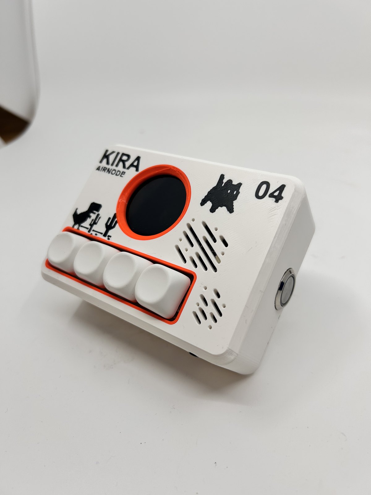
[!WARNING] AirNode is an ongoing, unfinished prototype. The PCB, enclosure, firmware, pin assignments, and documentation may change. This revision has not completed long-term validation, calibration, or product safety testing and is not production ready.
AirNode is an ESP32-C3 based indoor air-quality monitor in a compact 70 mm × 100 mm enclosure. It combines a round color display, four buttons, an audible alarm, and connections for environmental sensor modules.
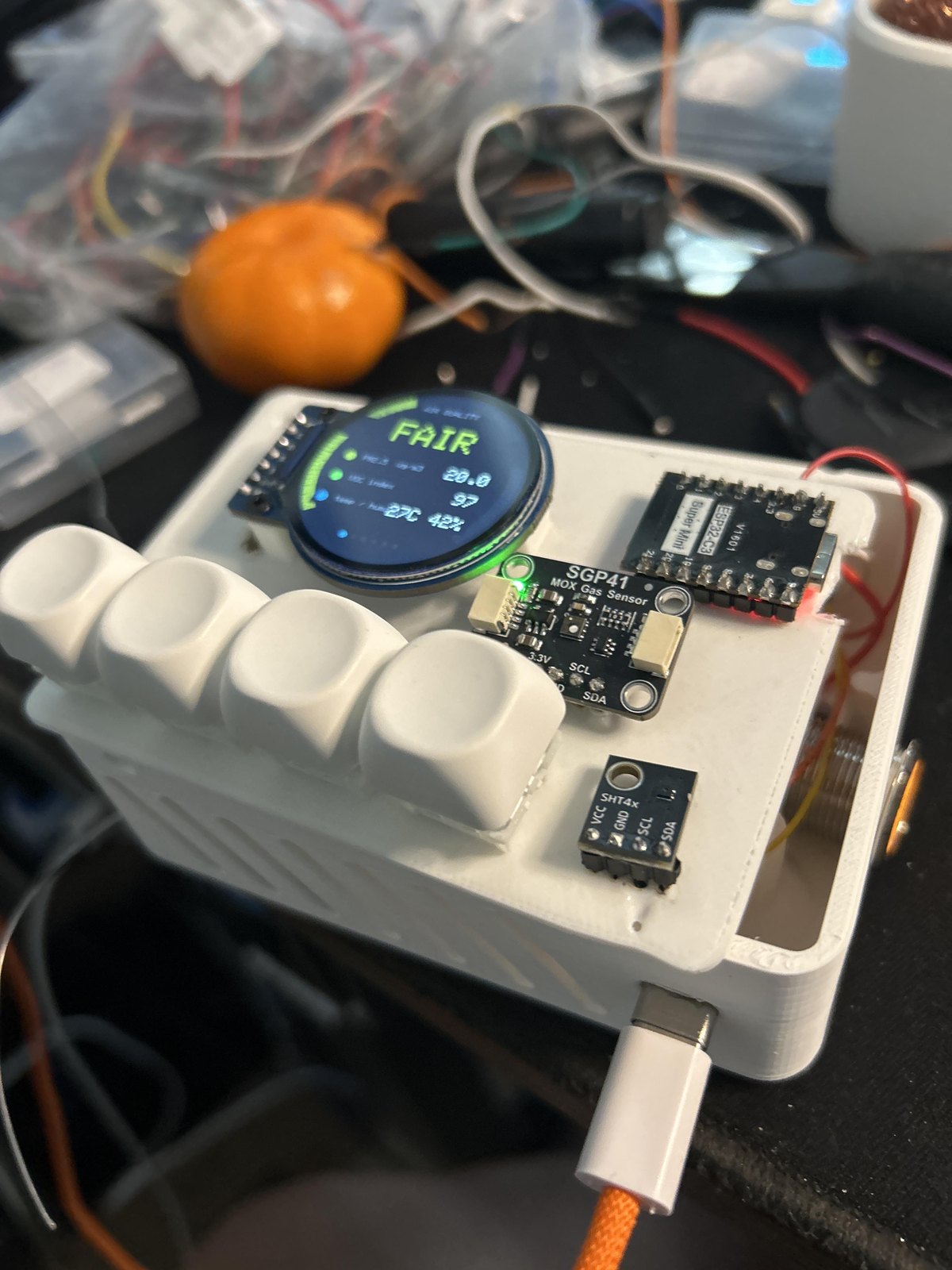
This repository records a working prototype and the next custom PCB revision. The photographed device uses development modules and point-to-point wiring; the KiCad design consolidates those connections onto a PCB.
| Area | Status |
|---|---|
| Schematic ERC | Pass: 0 violations |
| PCB connectivity | Pass: 0 unconnected items |
| PCB DRC | Pass: 0 violations and 0 unconnected pads |
| Enclosure | Prototype printed and assembled; PCB fit still requires physical verification |
| Firmware | Working prototype shown; source has not been added to this repository yet |
| Sensor calibration | In progress |
| Production testing | Not started |
Room Sensor.kicad_pro — KiCad projectRoom Sensor.kicad_sch — schematic sourceRoom Sensor.kicad_pcb — PCB layout sourceRoomSensor_Libraries/ — project symbols and footprintsV.2.3mf — printable enclosure sourceRoom Sensor.step — PCB 3D exportBOM.csv — bill of materialsmanufacturing/gerbers/ — fabrication outputs for the current revisionOpen Room Sensor.kicad_pro with KiCad 10 or newer. Review the schematic, PCB, and fabrication files together before ordering boards because the project remains under development.
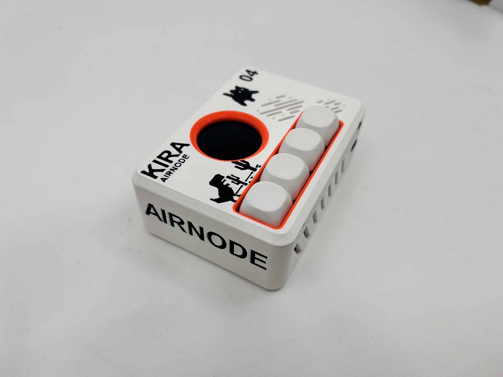
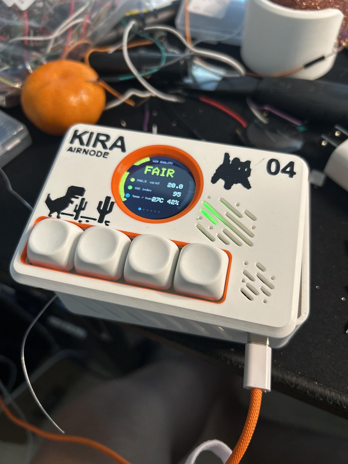
These photos show development wiring and module placement. They do not represent the final PCB assembly.
| Open prototype | Assembly in progress |
|---|---|
 | 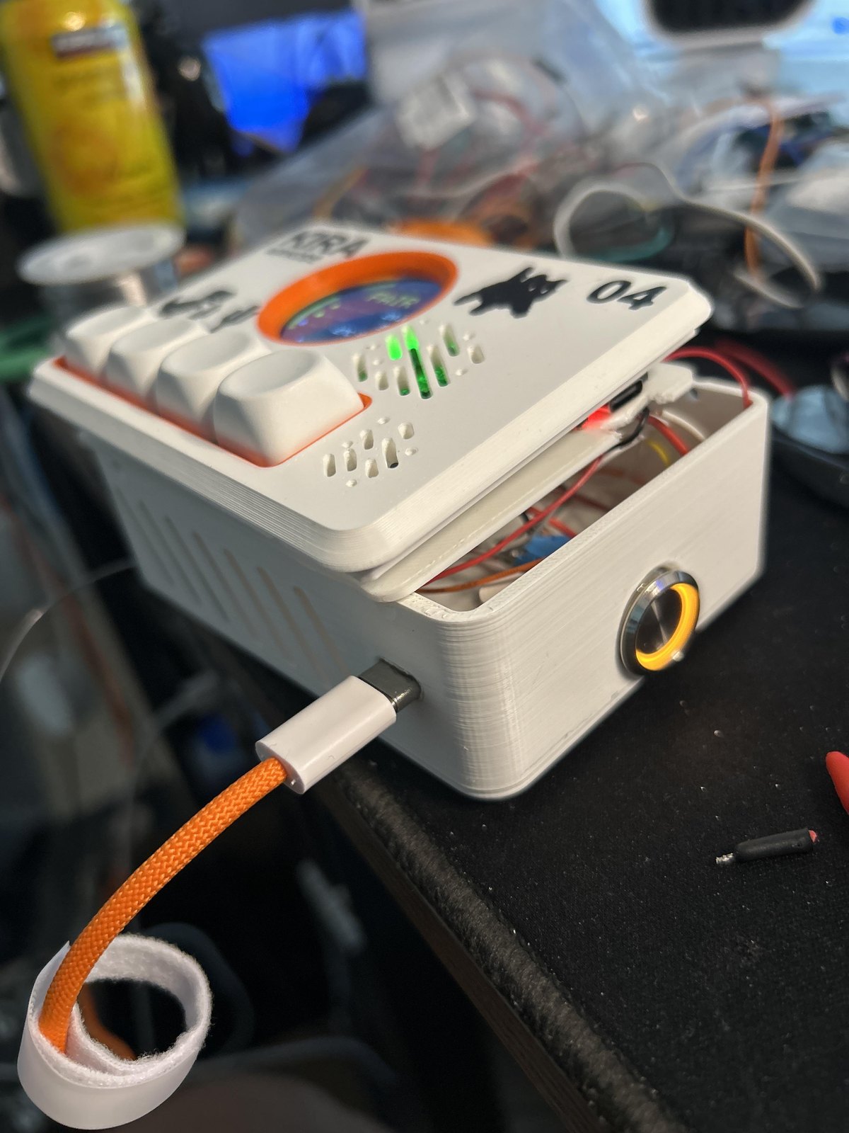 |
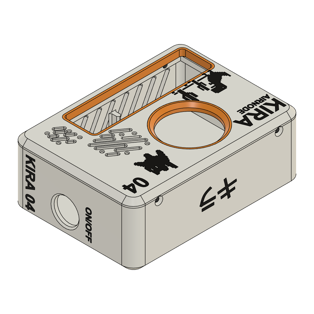
Hardware design files are released under the CERN Open Hardware Licence Version 2 — Strongly Reciprocal. See LICENSE.
| Qty | Value | Footprint | References |
|---|---|---|---|
| 4 | SW_Push | Button_Switch_Keyboard:SW_Cherry_MX_1.00u_PCB | SW1, SW2, SW3, SW4 |
| 2 | 5.1k | R_0805_2012Metric | R_CC1, R_CC2 |
| 2 | Conn_01x05 | Connector_PinHeader_2.54mm:PinHeader_1x05_P2.54mm_Vertical | SGP41, SPS30 |
| 2 | MountingHole_3.2mm_M3 | MountingHole:MountingHole_3.2mm_M3 | H1, H2 |
| 1 | 10k | Resistor_THT:R_Axial_DIN0207_L6.3mm_D2.5mm_P7.62mm_Horizontal | R1 |
| 1 | Conn_01x04 | Connector_PinHeader_2.54mm:PinHeader_1x04_P2.54mm_Vertical | SHT40 |
| 1 | Conn_01x07 | Connector_PinHeader_2.54mm:PinHeader_1x07_P2.54mm_Vertical | TFT1 |
| 1 | ESP32-C3_SUPERMINI_TH | ESP32-C3_SUPERMINI_TH:MODULE_ESP32-C3_SUPERMINI_TH | U2 |
| 1 | GCT USB4125-GF-A (1.00 mm shell stake) | USB_C_Receptacle_GCT_USB4125-xx-x_6P_TopMnt_Horizontal | J_USB |
| 1 | INSULATED WIRE | RoomSensor:Wire_Link_P12.70mm | JP1 |
| 1 | Piezo Buzzer | Buzzer_Beeper:Buzzer_12x9.5RM7.6 | BZ1 |
| 1 | SCD40 I2C | Connector_PinHeader_2.54mm:PinHeader_1x04_P2.54mm_Vertical | SCD40 |
| 1 | USB5V_SW_COM_SW_NO_GND | PinHeader_1x04_P2.54mm_Vertical | J_PWR |
It measures 70 × 100 mm and has 2 copper layers, 1.6 mm thick.
19 parts. The full list of its parts is on this page, with links to each part's symbol and footprint where PCBKit's library has them.
From the Syren0914/AirNode-Room-Sensor repository on GitHub, at the commit this page was made from: the board is Room Sensor.kicad_pcb and its schematic Room Sensor.kicad_sch. PCBKit opens the board in the browser, with nothing to install.
Its repository publishes it under the CERN-OHL-S-2.0 licence: you may reuse it on that licence's terms (keep the author's notice, and for a copyleft licence share your changes alike).

hackclub/OnBoard
💡 Join 1,000 teenagers and make your first PCB with a $100 grant!

polpo/picogus
Emulation of ISA sound cards and CD-ROM on Raspberry Pi Pico (GUS, SB/Adlib, MPU-401, Tandy, CMS, Panasonic CD-ROM) with USB mouse/joystick support


nkitanov/iaq_board
IAQ Board is a DIY (Do-It-Yourself) device for measuring internal air quality


Ardumower/ardumower
Develop an open source robotic lawn mower (HW+SW reference platform)

zmaker/arduino_cookbook
gli sketch del nuovo progetto Arduino Cookbook e dei video di YouTube