
2 layers47.6 × 27.3 mm
Autonomous indoor 3D scanning drone — RK4 physics, SLAM, frontier+coverage exploration, semantic reconstruction. Coverage parity on estimated pose vs ground truth.
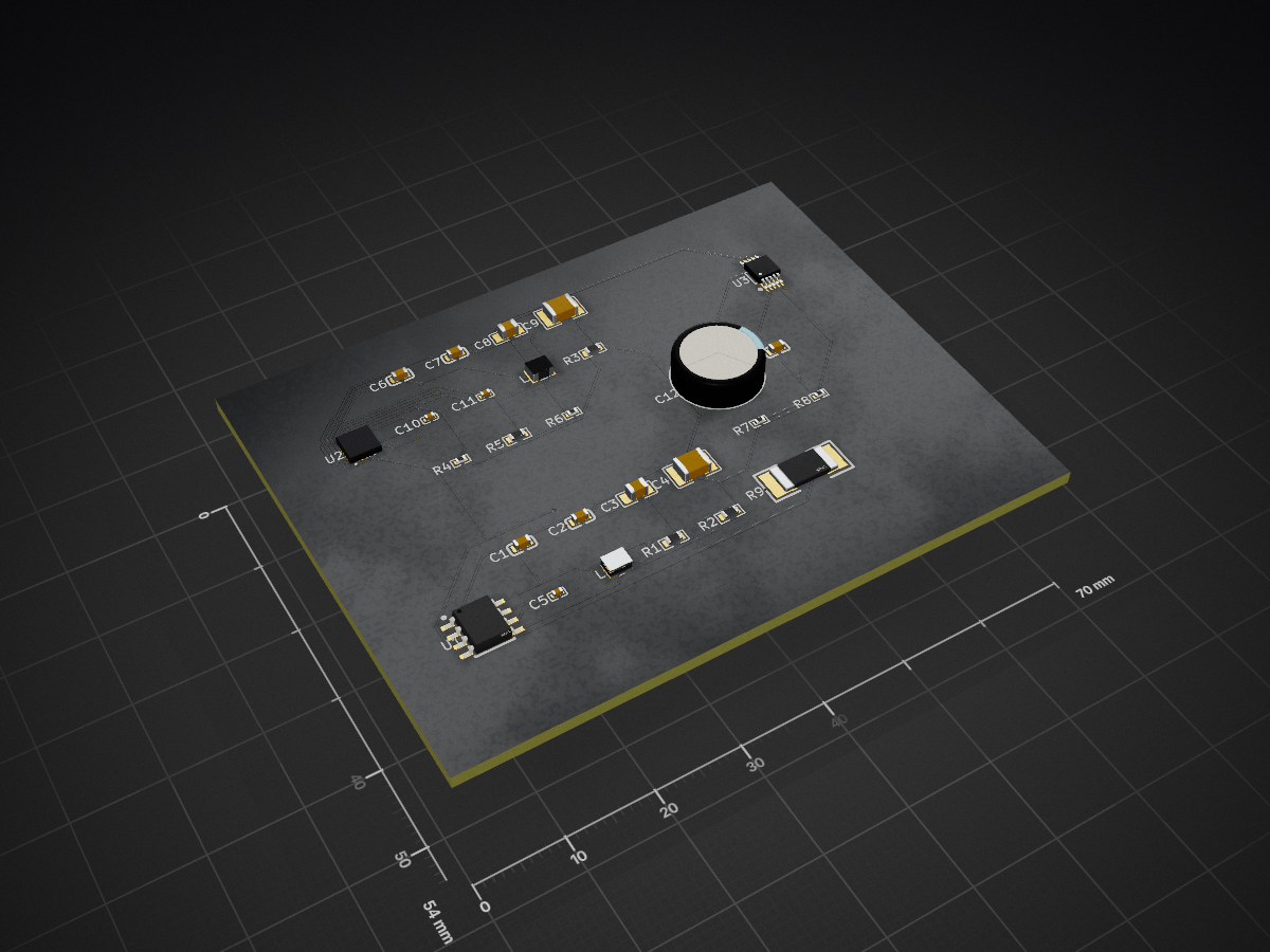
Psdb is an open-source printed circuit board by sypherdark, from the sypherdark/AetherScan repository on GitHub, published under the MIT licence. It is a 2-layer board of 70 × 54 mm with 27 parts on 19 nets, routed with 303 tracks and 11 vias.
Its parts include 13 capacitors, 9 resistors, 3 ICs and 2 inductors. It belongs with the robots and motor control boards of this library.
A drone that flies itself through an unknown indoor space, maps it in real time, and exports a 3D reconstruction.
AetherScan is a from-scratch indoor drone autonomy stack — 6-DoF physics, SLAM, frontier + coverage exploration, and semantic 3D reconstruction — built to the point where it demonstrates coverage parity flying on its own drifting pose estimate vs. flying on ground truth, in simulation. The remaining gaps to real hardware are identified, measured, and tracked in ROADMAP.md and REALWORLD_READINESS.md.
What actually runs: the
redwood_sim/Python backend (all physics, sensing, mapping, planning) streaming state over a WebSocket to a Next.js + React Three Fiber dashboard. You do not need ROS 2 or Gazebo to run AetherScan. Theaetherscan_ws/ROS 2 workspace is scaffolding for the eventual hardware-transfer target — see Repository layout.
Two independent processes with a single clean data contract between them.
┌──────────────────────────── redwood_sim/ (Python) ────────────────────────────┐
│                          ALL computation lives here                            │
│                                                                                │
│   physics.py ──► controls.py ──► navigation.py ──► discovery_map.py            │
│   (RK4 6-DoF      (cascaded      (frontier +        (log-odds occupancy        │
│    @ 500 Hz)       PID)           coverage A*)       grid, 0.2 m)              │
│        │              │               │                   │                    │
│   sensors.py    state_estimation.py   scan_matching.py    exporters.py         │
│   (168-ray       (drifting pose       (Olson 2009         (PLY / GLB / SVG     │
│    LiDAR sim)     estimate)            SLAM correction)     deliverables)       │
│                                                                                │
│                     bridge/server.py  ──►  WebSocket :8765  (20 Hz state)      │
└────────────────────────────────────────────────────────────────────────────────┘
                                      │
                          JSON over WebSocket
                                      │
┌──────────────────────── dashboard/ (Next.js + R3F) ───────────────────────────┐
│                       DISPLAY ONLY — zero physics, zero planning               │
│                                                                                │
│   ScanEnvironment   PointCloudRenderer   DiscoveredMap   PathVisualization     │
│   (loads scene GLB) (streams recon cloud)(occupancy grid)(planned path)        │
│                          MissionControl (start / stop / god-mode)              │
└────────────────────────────────────────────────────────────────────────────────┘
Invariant #0: the dashboard never computes physics or planning. It is a terminal. Every number it draws was produced in Python and shipped over the socket.
A single mission loop: the drone starts with an empty map (everything unknown). Each tick it raycasts a 168-ray LiDAR against the scene, folds the hits into a log-odds occupancy grid, picks the next frontier (using a FUEL-style global tour to avoid re-walking corridors), plans an obstacle-inflated A* path to it, and flies there under a cascaded PID controller — while a correlative scan-matcher bounds the drift in its self-estimated pose. Scanned points accumulate into a voxel-deduplicated cloud you can export as a colored PLY, a Poisson GLB mesh, and an SVG floor plan.
Requires Python 3.11+ (Apple Silicon: install via Homebrew — the system 3.9 segfaults on the Open3D BVH build) and Node 18+.
cd redwood_sim
./setup-macos.sh        # creates .venv (Python 3.11) and installs requirements.txt
#  …or manually:
# python3.11 -m venv .venv && .venv/bin/pip install -r requirements.txtOne-shot convenience script (starts the bridge headless, then the dashboard):
./run-aetherscan.sh --dashboard            # from repo root
./run-aetherscan.sh --dashboard --scene room_0    # pick a scene
# → http://localhost:3000
Or run them by hand in two terminals:
# Terminal 1 — physics bridge (WebSocket ws://127.0.0.1:8765)
cd redwood_sim
.venv/bin/python -m bridge --scene apartment_1

# Terminal 2 — dashboard
cd dashboard
npm install
npm run dev
# → http://localhost:3000
Open http://localhost:3000, pick a scene, hit Start Mission, and watch the drone
explore. The fuchsia GOD button enables ~3× time acceleration.
Note on scene meshes: the dashboard's visual
.glbmeshes and the backend's collision meshes are not in the repo (they're hundreds of MB, generated from the Meta Replica dataset). The physics bridge runs fine without them; the 3D viewport will be empty until you generate the assets — see Scene assets.
cd redwood_sim
.venv/bin/python -m pytest tests -q        # 8 state-estimation regression tests
The bridge speaks JSON over ws://127.0.0.1:8765, broadcasting state at 20 Hz.
| Message | Direction | Payload |
|---|---|---|
hello | server→client | visual_mesh_url, scene_bounds (ROS ENU frame, never pre-transformed) |
scene_changed | server→client | same as hello, on scene switch |
state (20 Hz) | server→client | position, quaternion, velocity, tilt, altitude, coverage_pct, total_points, path, discovery_map, map_points (new points since last frame), localization{ mode, pos_drift_m, yaw_drift_deg, slam_corrections, slam_match_score, slam_health }, god_mode |
set_scene | client→server | switch the active scene |
set_god_mode | client→server | toggle 3× time acceleration |
export_scan | client→server | run the PLY/GLB/SVG export pipeline async; replies export_started / export_complete{ urls, files, errors } |
Reconstruction points are streamed as deltas (map_points = new-since-last-frame),
and the frontend uploads only new points into a preallocated 500k buffer — it never
rebuilds the cloud. All server sends pass through a single asyncio.Lock so a
scene-switch can't race the 20 Hz broadcast and drop the connection.
Coordinate convention: everything in Python is Z-up ROS / ENU (X=forward,
Y=left, Z=up). The Three.js layer applies rosToThree(x,y,z) = [x, z, -y] exactly
once, at the scene group. scene_bounds cross the wire in the ROS frame, untouched.
Bridge CLI: python -m bridge --scene <id> [--host 127.0.0.1] [--port 8765] [--rate 20] [--voxel 0.03] [--dt 0.002]
| Module | What it does | Notable detail |
|---|---|---|
core/physics.py | 6-DoF quadrotor rigid body, RK4 @ 500 Hz | ~1.45 kg frame, drag, ground effect, Dryden wind; collision resolved per micro-step to prevent tunneling |
core/controls.py | Cascaded PID: position→velocity→attitude→thrust | Correct ZYX-Euler world→body tilt mapping (a swapped-axis bug previously made it fly perpendicular to its command) |
core/sensors.py | 168-ray LiDAR (7 rings × 24), range/normal noise | Configurable FOV (360° RPLIDAR baseline; 87° = D435 camera-class) |
core/discovery_map.py | Log-odds occupancy grid, 0.2 m | Floor hits are FREE at flight altitude; noisy returns can't flip a cell; compact body model fits 0.8 m doorways |
core/navigation.py | Frontier + coverage exploration, A* path-following | FUEL-style global tour ordering: +15–56 % coverage per meter |
core/state_estimation.py | Drifting, noisy pose estimate (the sim-to-real seam) | config.use_estimated_pose — off for the clean demo |
core/scan_matching.py | Correlative scan-matcher (Olson 2009) + keyframe SLAM | Bounds drift to 0.04–0.10 m vs. 0.14→0.33 m unbounded |
core/exporters.py | PLY (semantic-colored) / GLB (Poisson) / SVG floor plan | Written to dashboard/public/exports/ |
Headline result: with use_estimated_pose=True, the drone flies entirely on its
own estimate — discovery map, frontier goals, path-following, and trajectory setpoints
all live in the estimated frame — and reaches coverage parity with ground-truth
navigation (apartment_1 35.2 % vs 37.0 %; room_0 89.8 % vs 87.2 %), with lower tilt
and fewer wall contacts. Full audit: REALWORLD_READINESS.md.
The simulation defines a real aircraft, and hardware/ designs it to
match — kept in accordance with the software by a checker that fails if the CAD
ever drifts from the physics model (hardware/cad/check_against_software.py).
A 2-page investor brief built from real captured system output lives in presentation/.
AetherScan ships with 18 Meta Replica scenes (apartment_0–2, frl_apartment_0–5,
office_0–4, room_0–2). For licensing and size reasons the dataset and generated
meshes are not committed. To populate the 3D viewport:
redwood_sim/data/replica/<id>/.python3 scripts/convert_replica_to_glb.py # → dashboard/public/meshes/<id>.glb
python3 scripts/build_collision_meshes_fast.py # → <id>_collision.ply (~120k tris)The physics bridge runs without these (it falls back to built-in/procedural geometry); they only affect what the dashboard renders and what the backend raycasts against.
redwood_sim/          ← THE WORKING SYSTEM (Python: physics, sensing, mapping, planning, SLAM)
  core/               ← physics, controls, sensors, discovery_map, navigation, state_estimation, scan_matching, exporters
  bridge/server.py    ← WebSocket bridge :8765
  simulation/engine.py← fixed-timestep mission loop
  tests/              ← state-estimation regression suite
dashboard/            ← Next.js + React Three Fiber UI (display only)
  src/components/three/  ← scene, point cloud, occupancy, path, drone renderers
  src/lib/            ← WebSocket client, scene registry, ROS↔Three transforms
scripts/              ← Replica → GLB conversion, collision-mesh builder, semantics
hardware/             ← THE PHYSICAL DRONE (design, CAD, electrical) — see below
  design/             ← multidisciplinary design reviews & converged spec
  cad/                ← parametric airframe (build123d) + software-accordance checker
  electrical/pcb/     ← code-defined PCB (atopile) + KiCad layout/render/gerbers
  specs/ · bom/       ← system spec, mass/power/inertia budgets, real-parts BOM
presentation/         ← 2-page investor brief (PDF) built from real system output
aetherscan_ws/        ← ROS 2 (Humble) workspace — HARDWARE-TRANSFER TARGET, not required to run the sim
docker/ ← optional containerized sim + dashboardaetherscan_ws/ contains a full ROS 2 package set (description, gazebo,
navigation, perception, slam, control, mission, bringup). It is the
intended deployment target for porting the autonomy stack onto a real airframe
(RViz config, URDF/Xacro drone model, Gazebo worlds, launch files). It is not the
path that runs the simulation you see in the dashboard — that's redwood_sim/. Treat
the ROS 2 side as scaffolding under active development, not a finished product.
The algorithms are drawn from the literature and measured against it:
aetherscan_ws/ is scaffolding, not a validated flight stack.See ROADMAP.md for the phased plan.
MIT — see LICENSE.
| Qty | Value | Footprint | References |
|---|---|---|---|
| 5 | 100nF ±10% | YAGEO_CC0603KRX7R9BB104:C0603 | C1, C2, C6, C7, C13 |
| 2 | 10kΩ ±1% | UNI_ROYAL_0603WAF1002T5E:R0603 | R1, R5 |
| 2 | 1µF ±10% | Samsung_Electro_Mechanics_CL05A105KA5NQNC:C0402 | C5, C11 |
| 2 | 22µF ±20% | HRE_CGA0805X5R226M350MT:C0805 | C3, C8 |
| 2 | 4.7kΩ ±1% | UNI_ROYAL_0402WGF4701TCE:R0402 | R7, R8 |
| 2 | 47µF ±10% | Murata_Electronics_GRM32ER61C476KE15L:C1210 | C4, C9 |
| 1 | Texas_Instruments_LMR33630ADDAR:ESOP-8_L4.9-W3.9-P1.27-LS6.0-TL-EP | U1 | |
| 1 | Texas_Instruments_TPS568230RJER:QFN-20_L3.0-W3.0-P0.45-BL-EP1.0 | U2 | |
| 1 | Texas_Instruments_INA226AIDGSR:MSOP-10_L3.0-W3.0-P0.50-LS5.0-BL | U3 | |
| 1 | 100kΩ ±1% | UNI_ROYAL_0402WGF1003TCE:R0402 | R4 |
| 1 | 13kΩ ±1% | FOJAN_FRC0603F1302TS:R0603 | R3 |
| 1 | 2.2nF ±10% | FH_0402B222K500NT:C0402 | C10 |
| 1 | 2mΩ ±1% | Milliohm_HoLLR2512_3W_2mR_1:RES-SMD_L6.4-W3.2-1 | R9 |
| 1 | 40.2kΩ ±1% | UNI_ROYAL_0603WAF4022T5E:R0603 | R2 |
| 1 | 470µF ±20% | AISHI_ERJ1HM471G16C36T:CAP-TH_BD10.0-P5.00-D1.0-FD | C12 |
| 1 | 73.2kΩ ±1% | UNI_ROYAL_0402WGF7322TCE:R0402 | R6 |
| 1 | L 2.2µH ±20% | cjiang_FTC252012S2R2MBCA:IND-SMD_L2.5-W2.0_MHCHL2520 | L2 |
| 1 | L 4.7µH ±20% | cjiang_FTC252010S4R7MBCA:IND-SMD_L2.5-W2.0-VLS252012CX-150M | L1 |
It measures 70 × 54 mm and has 2 copper layers, 1.6 mm thick.
27 parts. The full list of its parts is on this page, with links to each part's symbol and footprint where PCBKit's library has them.
From the sypherdark/AetherScan repository on GitHub, at the commit this page was made from: the board is hardware/electrical/pcb/elec/layout/psdb/psdb.kicad_pcb and its schematic hardware/electrical/pcb/elec/layout/psdb/psdb.kicad_sch. PCBKit opens the board in the browser, with nothing to install.
Its repository publishes it under the MIT licence: you may reuse it on that licence's terms (keep the author's notice, and for a copyleft licence share your changes alike).

hackclub/OnBoard
💡 Join 1,000 teenagers and make your first PCB with a $100 grant!


CRImier/MyKiCad
My KiCad boards. Can't be bothered uploading individually anymore, so here you go.

pjgpetecodes/pico-streamdeck
This project is an OBS Controller using a Raspberry Pi Pico and CircuitPython.

freeDSP/freeDSP-aurora
freeDSP ADAU1452 with 8 analog input, 8 analog outputs, S/P-DIF I/O, ADAT I/O, USB Audio Class2, WiFi, Bluetooth

ugcs/ddc
Drone Show Software is software designed for drone shows, allowing flight path planning as well as control of dozens of drones simultaneously in a synchronized manner.