

4 layers160 × 100 mm
 Synthron/ModLab3
Modular Electronics Workstation
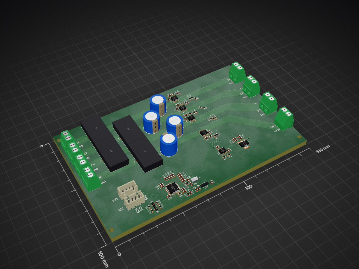
Current sensor filter is an open-source printed circuit board by Synthron, from the Synthron/ModLab repository on GitHub. It is a 4-layer board of 160 × 100 mm with 95 parts on 67 nets, routed with 434 tracks and 266 vias.
It is built around the LM2904 and BSS138. Its parts include 37 capacitors, 29 resistors, 10 connectors, 7 ICs and 4 inductors. It belongs with the sensors and measurement boards and the STM32 boards of this library.
The ModLab is designed to be housed in a 19" Rack with 3U.
It is the improved version of the (failed) Arduino Workstation I built a long time ago.
But now It will be bigger, better and way too complicated.
Work in Progress
ModLab Lib Tracker:
| Qty | Value | Footprint | References |
|---|---|---|---|
| 13 | 100n | Capacitor_SMD:C_0805_2012Metric | C1, C2, C3, C8, C13, C14, C15, C20, C21, C23, C25, C30, C35 |
| 12 | 1n | Capacitor_SMD:C_0805_2012Metric | C9, C10, C11, C12, C16, C17, C18, C19, C24, C27, C31, C33 |
| 9 | 12k | Resistor_SMD:R_0805_2012Metric | R9, R10, R11, R12, R22, R26, R27, R28, R29 |
| 6 | 100 | Resistor_SMD:R_0805_2012Metric | R1, R2, R3, R4, R20, R24 |
| 5 | 1µ | Capacitor_SMD:C_0805_2012Metric | C22, C32, C34, C36, C37 |
| 5 | 3k9 | Resistor_SMD:R_0805_2012Metric | R5, R6, R7, R8, R21 |
| 4 | 10k | Resistor_SMD:R_0805_2012Metric | R13, R14, R18, R25 |
| 4 | 150µH | Inductor_THT:L_Toroid_Vertical_L25.4mm_W14.7mm_P12.20mm_Vishay_TJ5_BigPads | L1, L2, L3, L4 |
| 4 | 2200µ | Capacitor_THT:CP_Radial_D12.5mm_P5.00mm | C4, C5, C6, C7 |
| 4 | ACS723xLCTR-05AB | Package_SO:SOIC-8_3.9x4.9mm_P1.27mm | U1, U2, U3, U4 |
| 2 | 20p | Capacitor_SMD:C_0805_2012Metric | C28, C29 |
| 2 | BSS138 | Package_TO_SOT_SMD:SOT-23 | Q1, Q2 |
| 1 | -15V IN | TerminalBlock:TerminalBlock_bornier-2_P5.08mm | J4 |
| 1 | -15V OUT | TerminalBlock:TerminalBlock_bornier-2_P5.08mm | J8 |
| 1 | 100k | Resistor_SMD:R_0805_2012Metric | R16 |
| 1 | 15V IN | TerminalBlock:TerminalBlock_bornier-2_P5.08mm | J3 |
| 1 | 15V OUT | TerminalBlock:TerminalBlock_bornier-2_P5.08mm | J7 |
| 1 | 18k | Resistor_SMD:R_0805_2012Metric | R19 |
| 1 | 1M | Resistor_SMD:R_0805_2012Metric | R23 |
| 1 | 20k | Resistor_SMD:R_0805_2012Metric | R15 |
| 1 | 24V IN | TerminalBlock:TerminalBlock_bornier-2_P5.08mm | J2 |
| 1 | 24V OUT | TerminalBlock:TerminalBlock_bornier-2_P5.08mm | J6 |
| 1 | 4µ7 | Capacitor_SMD:C_0805_2012Metric | C26 |
| 1 | 5V IN | TerminalBlock:TerminalBlock_bornier-2_P5.08mm | J1 |
| 1 | 5V OUT | TerminalBlock:TerminalBlock_bornier-2_P5.08mm | J5 |
| 1 | 68k | Resistor_SMD:R_0805_2012Metric | R17 |
| 1 | 8MHz | Crystal:Crystal_SMD_5032-4Pin_5.0x3.2mm | Y1 |
| 1 | AP1117-33 | Package_TO_SOT_SMD:SOT-223-3_TabPin2 | U6 |
| 1 | I2C | Connector_JST:JST_XH_B4B-XH-A_1x04_P2.50mm_Vertical | J10 |
| 1 | LM2904 | Package_SO:SOIC-8_3.9x4.9mm_P1.27mm | U5 |
| 1 | SMB-001 | eigene:SMB-001 | FB1 |
| 1 | STM32F103C8Tx | Package_QFP:LQFP-48_7x7mm_P0.5mm | U7 |
| 1 | SWD | Connector_JST:JST_XH_B4B-XH-A_1x04_P2.50mm_Vertical | J9 |
The 91 most common of 95 parts.
It measures 160 × 100 mm and has 4 copper layers, 4.69 mm thick.
95 parts, built around the LM2904 and BSS138. The full list of its parts is on this page, with links to each part's symbol and footprint where PCBKit's library has them.
From the Synthron/ModLab repository on GitHub, at the commit this page was made from: the board is Hardware/V3/current_sensor_filter/current_sensor_filter.kicad_pcb and its schematic Hardware/V3/Bustermination/Bustermination.kicad_sch. PCBKit opens the board in the browser, with nothing to install.
Its repository states no licence, so its author keeps all rights: ask Synthron before reusing the design.


mgsilva/TCC_hardware_aquisicao
Layout da PCB do sistema de aquisição utilizado na projeto

peterkrull/quad
Firmware, hardware and documentation for my autonomous quad copter project

DanielMartensson/STM32-PLC
STM32 microcontroller with lots of periferials such as ADC, differential ADC, Input Capture, PWM, USB, Encoder, DAC, Digital Input, RTC, CAN-bus + Alarm etc.

michaelruppe/FSAE
Projects for Formula SAE Electric Vehicle competition (Australia 2019/2020)


M0LTE/pi-transceiver
An attempt to build a complete ham radio transceiver around a Raspberry Pi

frohro/WWU-VNA
An Inexpensive Vector Network Analyzer Project for the Walla Walla University Electronics II Class

PySpice-org/eda-rw
Python library to read/write KiCad and LibrePCB Sexpr file format