2 layers110 × 82.5 mm

 superna9999/tinyci3
tinyci
Tinyci main is an open-source printed circuit board by superna9999, from the superna9999/tinyci repository on GitHub. It is a 2-layer board of 110 × 82.5 mm with 54 parts on 55 nets, routed with 312 tracks and 82 vias.
It is built around the AMS1117-3.3 and BC817-25. Its parts include 13 connectors, 9 resistors, 9 diodes, 6 capacitors and 4 transistors.


General Concept:
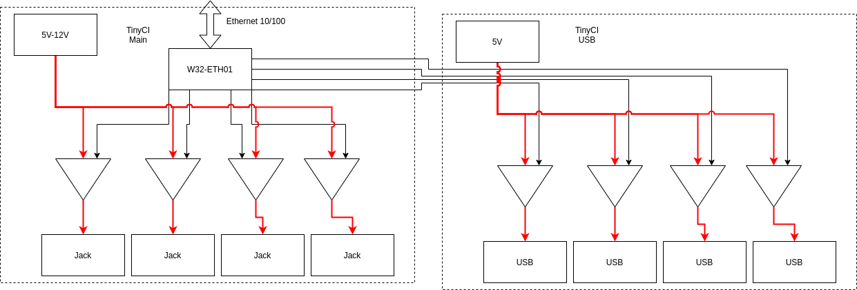
Relay board controlled by a W32-ETH01 module.
Input: 5V
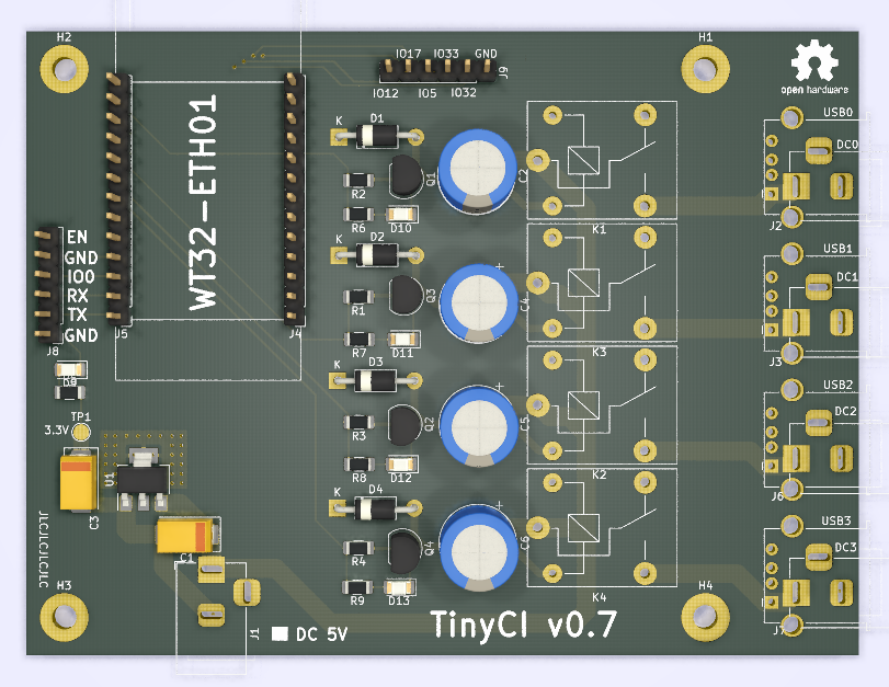
Produced:
ESP32 Firmware: see firmware/tinyci-fw/
Remote Relay Control script: see firmware/tinyci-fw/tinyci-relay.py
Secondary Relay board controlled by the W32-ETH01 on the main board.
Input: 5V to 12V
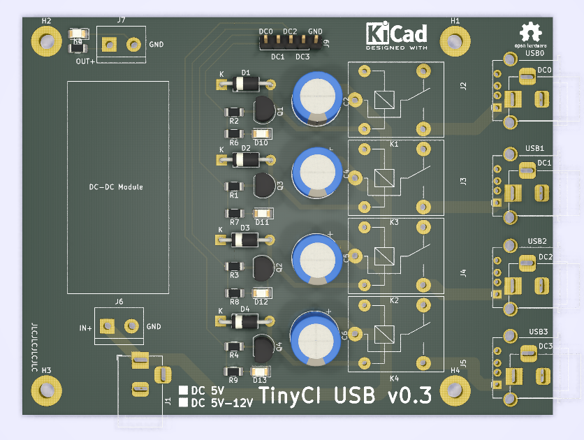
Produced:
Quad FTDI board + breakout of all FTDI I/Os with the TinyCi form factor + holes to hook a Pi/LaFrite/LePotato to control the FTDI + TinyCi USBs.
Input: USB
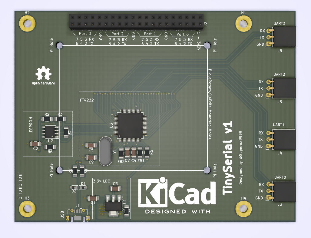
Produced:
CERN OPEN HARDWARE LICENCE v1.1| Qty | Value | Footprint | References |
|---|---|---|---|
| 5 | 220R | Resistor_SMD:R_1206_3216Metric | R5, R6, R7, R8, R9 |
| 5 | Jack-DC | Connector_BarrelJack:BarrelJack_Horizontal | J1, J2, J3, J6, J7 |
| 5 | LED | LED_SMD:LED_1206_3216Metric | D9, D10, D11, D12, D13 |
| 4 | 1000uF | Capacitor_THT:CP_Radial_D10.0mm_P5.00mm | C2, C4, C5, C6 |
| 4 | 1K | Resistor_SMD:R_1206_3216Metric | R1, R2, R3, R4 |
| 4 | BC817-25 | Package_TO_SOT_SMD:SOT-23 | Q1, Q2, Q3, Q4 |
| 4 | MountingHole_Pad | MountingHole:MountingHole_3.2mm_M3_Pad | H1, H2, H3, H4 |
| 4 | S1BB-13-F | Diode_SMD:D_SMB_Handsoldering | D1, D2, D3, D4 |
| 4 | SANYOU_SRD_Form_C | Relay_THT:Relay_SPDT_SANYOU_SRD_Series_Form_C | K1, K2, K3, K4 |
| 4 | USB_A_Stacked | Connector_USB:USB_A_Wuerth_61400826021_Horizontal_Stacked | J10, J11, J12, J13 |
| 2 | 10uF | Capacitor_Tantalum_SMD:CP_EIA-7343-31_Kemet-D | C1, C3 |
| 2 | Conn_01x06_Male | Connector_PinHeader_2.54mm:PinHeader_1x06_P2.54mm_Vertical | J8, J9 |
| 2 | Conn_01x13_Male | Connector_PinHeader_2.54mm:PinHeader_1x13_P2.54mm_Vertical | J4, J5 |
| 1 | AMS1117-3.3 | Package_TO_SOT_SMD:SOT-223-3_TabPin2 | U1 |
| 1 | LOGO | TinyCI:just-ci-it | G*** |
| 1 | TestPoint | TestPoint:TestPoint_Pad_D2.0mm | TP1 |
The 52 most common of 54 parts.
It measures 110 × 82.5 mm and has 2 copper layers, 1.6 mm thick.
54 parts, built around the AMS1117-3.3 and BC817-25. The full list of its parts is on this page, with links to each part's symbol and footprint where PCBKit's library has them.
From the superna9999/tinyci repository on GitHub, at the commit this page was made from: the board is tinyci-main/tinyci-main.kicad_pcb and its schematic tinyci-main/USB_Connectors.kicad_sch. PCBKit opens the board in the browser, with nothing to install.
Its repository states no licence, so its author keeps all rights: ask superna9999 before reusing the design.


AzonInc/Doorman
ESP32-S3 based Intercom Gateway (TCS / Koch / Niko / Scantron / Analogue Systems)

DimitriOnLSD/imu-rc
Gesture-based RC car controller using ESP32-S3, BLE, LSM6DSO IMU, OLED display, and LiPo battery with USB-C charging.

mlab-modules/BATDATUNIT01
Multiple parallel Li-ion 18650 battery cell module with BMS and data storage with MCU control.


AstroMeters/AMFOC01
Open-source USB-C precize motorized telescope focuser with PC and manual control support.

JanClyde05/Road-Accident-Monitoring-System
This directory contains the planning, specification, and initial KiCad project for RAMS Wearable PCB Revision C. Do not fabricate from this directory yet -- manual schematic wiring and DRC verification are still needed.

ThunderFly-aerospace/TFUNIPAYLOAD01
Universal interface for TF-ATMON sensor payload.

falseywinchnet/hf-active-antennas
Open-hardware HF receive-antenna amplifiers: zero-flux loop amp, loop LNA, mini-whip. LTspice models, KiCad boards, JLCPCB packages. see license