2 layers100 × 100 mm
HotBox
sundr007/HotBox
A benchtop thermal Chamber used to test electronics at elevated ambient temperature. Kicad PCB, STM32 firmware, OpenScad Mechanical
38 parts1GPL-2.0

 sundr007/HotBox1
A benchtop thermal Chamber used to test electronics at elevated ambient temperature. Kicad PCB, STM32 firmware, OpenScad Mechanical
HotBox is an open-source printed circuit board by sundr007, from the sundr007/HotBox repository on GitHub, published under the GPL-2.0 licence. It is a 2-layer board of 100 × 100 mm with 43 parts on 45 nets, routed with 246 tracks and 11 vias.
It is built around the MCP1416-E/OT and BSC028N06LS3 G. Its parts include 14 resistors, 4 capacitors, 3 transistors, 3 connectors and 2 ICs. It belongs with the AVR (ATmega, ATtiny) boards of this library.


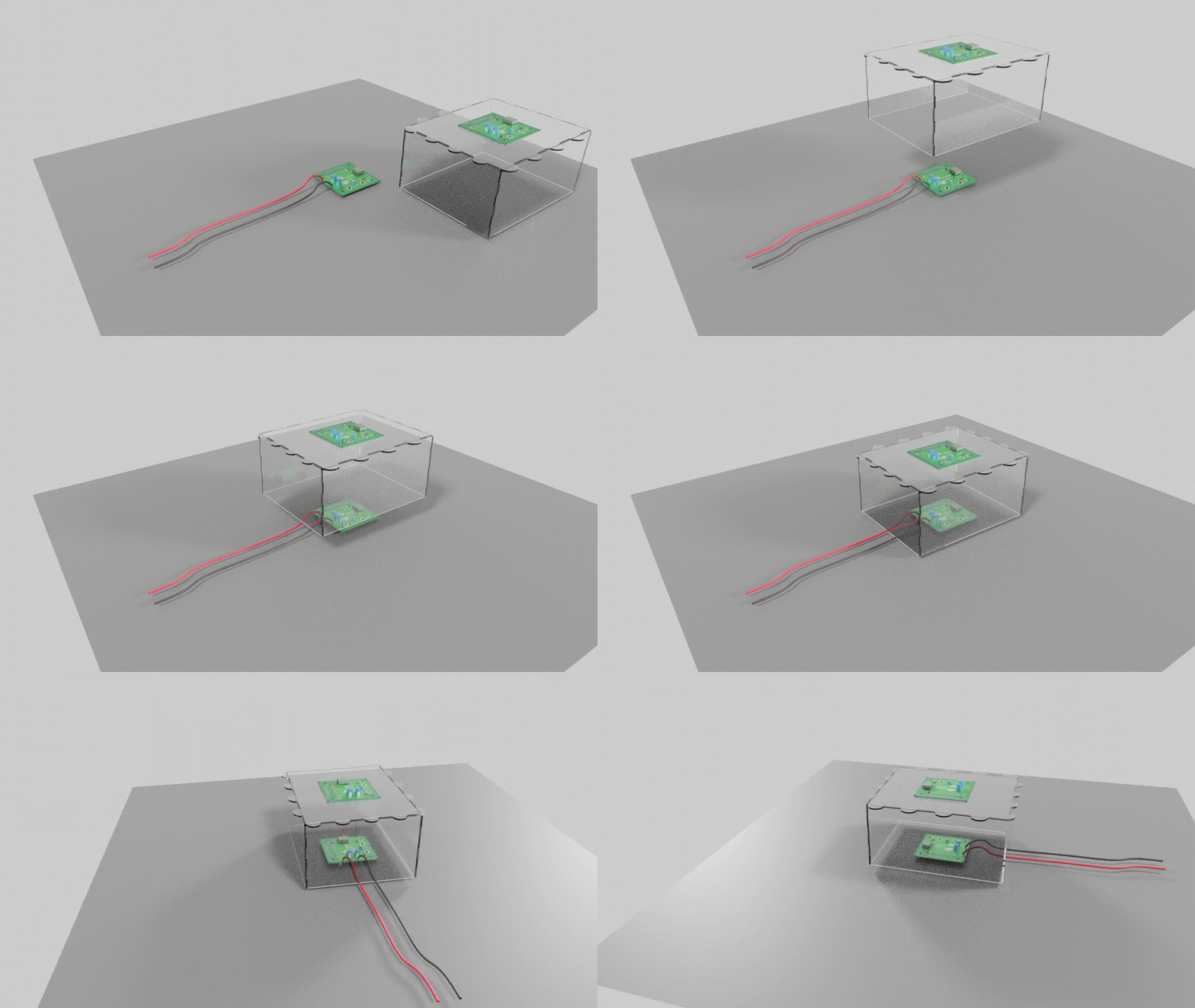
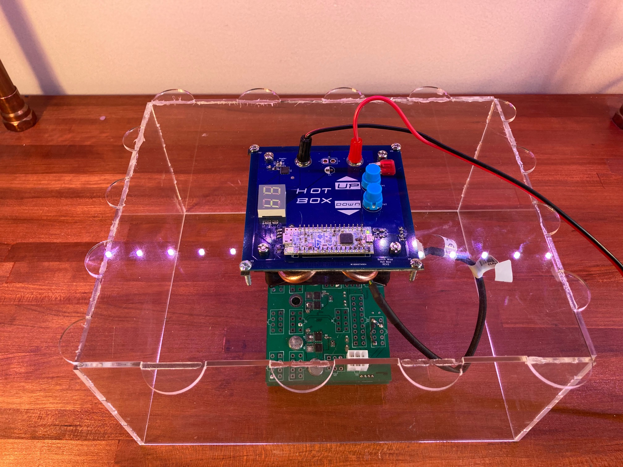
I use this when I'm testing electronics on my benchtop. I put this box on top of what I'm testing to raise the ambient temperature. This is convenient because I can leave my probes and other wires hooked up as is. This box can raise the ambient temperature up to 55C.
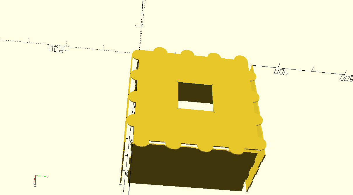
The design consists of a finger edge laser cut acrylic box that has a circuit board assembly mount in the top center of it. I put foam on the bottom edge of the box so it can nicely sit on top of wires and cables without air gaps.
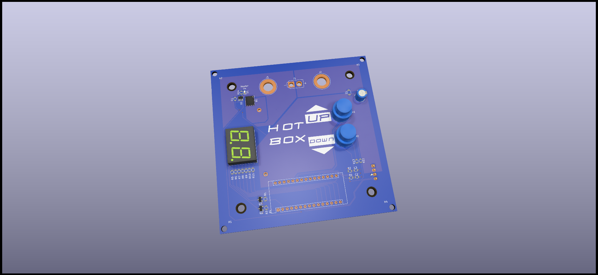
The circuit board assembly consists of a 2 layer PCB meant to fit PCBWAY's cheap board special (hint,they're $1 a piece for QTY 5). On the PCB there is a ST NUCLEO-G431KB board which is an easy way to add a microcontroller. There's 2 buttons to control temperature setpoint, a 7 segment display to display temperature, a peltier plate that acts as the heating element, and an Intel LGA1155 processor fan to spread the heat from the peltier plate.
I have built the current revision and found that it works as expected and I'm able to use it as I debug and test my electronics.
| Qty | Value | Footprint | References |
|---|---|---|---|
| 8 | 330 | Artesyn:0805_R | R5, R6, R7, R8, R9, R10, R11, R14 |
| 6 | 10K | Artesyn:0805_R | R1, R2, R3, R4, R12, R13 |
| 4 | MountingHole | MountingHole:MountingHole_3.2mm_M3 | H1, H2, H3, H4 |
| 3 | 0.1uF | Artesyn:0805_C | C1, C2, C3 |
| 2 | 2N3904 | Package_TO_SOT_SMD:SOT-23 | Q2, Q3 |
| 2 | Conn_01x01 | Connector:Banana_Jack_1Pin | J2, J3 |
| 2 | SW_Push_4PIN | Artesyn:SW_D6 | SW1, SW2 |
| 2 | Thermistor_NTC | Artesyn:0805_R | TH1, TH2 |
| 1 | 10uF | Capacitor_THT:CP_Radial_D6.3mm_P2.50mm | C4 |
| 1 | Arduino_Nano_v3.x | Module:Arduino_Nano | A1 |
| 1 | BSC028N06LS3 | Package_TO_SOT_SMD:TDSON-8-1 | Q1 |
| 1 | Conn_01x02 | AMASS:AMASS_XT30U-M_1x02_P5.0mm_Vertical | J1 |
| 1 | DA04-11CGKWA | Display_7Segment:DA04-11CGKWA | U2 |
| 1 | Fan | Artesyn:LGA1155_FAN | M2 |
| 1 | Fan_4pin | Connector:FanPinHeader_1x04_P2.54mm_Vertical | M1 |
| 1 | Fuse | Artesyn:1206_R | F1 |
| 1 | LED | LED_SMD:LED_0603_1608Metric | D1 |
| 1 | LOGO | Artesyn:HOTBOX | G*** |
| 1 | LOGO | Artesyn:UP | G*** |
| 1 | LOGO | Artesyn:DOWN | G*** |
| 1 | MCP1416 | Package_TO_SOT_SMD:SOT-23-5 | U1 |
| 1 | Peltier_Element | Artesyn:Peltier_40x40 | PE1 |
sundr007/HotBox
A benchtop thermal Chamber used to test electronics at elevated ambient temperature. Kicad PCB, STM32 firmware, OpenScad Mechanical

sundr007/HotBox
A benchtop thermal Chamber used to test electronics at elevated ambient temperature. Kicad PCB, STM32 firmware, OpenScad Mechanical


enkhbold470/spinner
12-24 V FOC BLDC motor controller: STM32G431, three IR2104 half bridges with 60 V MOSFETs, MT6701 encoder, CAN FD. 4-layer KiCad 10 board.

felixznr/ALBERT
Albert I was a rhesus macaque monkey and the first mammal launched on a rocket (V-2 Rocket "Blossom No. 3") on June 18, 1948.

M-Welsch/base-pcb-power
Backup Server Circuit Board that contains power management and sbu

pez-globo/pufferfish-electronics
Circuit schematics and PCB layouts for the Pufferfish ventilator.


zhaque3/DC-DC-Boost-Converter
A repository consisting of the PCB Design and firmware for DC-DC Boost converter on the University of Alberta EcoCar vehicle.
It measures 100 × 100 mm and has 2 copper layers, 1.6 mm thick.
43 parts, built around the MCP1416-E/OT and BSC028N06LS3 G. The full list of its parts is on this page, with links to each part's symbol and footprint where PCBKit's library has them.
From the sundr007/HotBox repository on GitHub, at the commit this page was made from: the board is EE - Kicad/REV1/HotBox.kicad_pcb and its schematic EE - Kicad/REV3/HotBox.kicad_sch. PCBKit opens the board in the browser, with nothing to install.
Its repository publishes it under the GPL-2.0 licence: you may reuse it on that licence's terms (keep the author's notice, and for a copyleft licence share your changes alike).