
2 layers407 × 184 mm
TRS-80-Model I G E1
RetroStack/TRS-80-Model-I-G-E1
Hardware Replica of the TRS-80 Model I Revision G
230 parts57MIT

 SukkoPera/WheelOfJoyMini2
4-player joystick adapter for the Commodore 16, 116 and Plus/4 with 2-button support
WheelOfJoy is an open-source printed circuit board by SukkoPera, from the SukkoPera/WheelOfJoyMini repository on GitHub. It is a 2-layer board of 47.8 × 45.4 mm with 26 parts on 47 nets, routed with 520 tracks and 120 vias.
It is built around the 74LS153DC. Its parts include 5 connectors, 4 capacitors and 3 ICs. It belongs with the retro computing and games and keyboards and input boards of this library.
WheelOfJoyMini is an Open Hardware 4-player joystick adapter for the Commodore 16, 116 and Plus/4 with 2-button support.
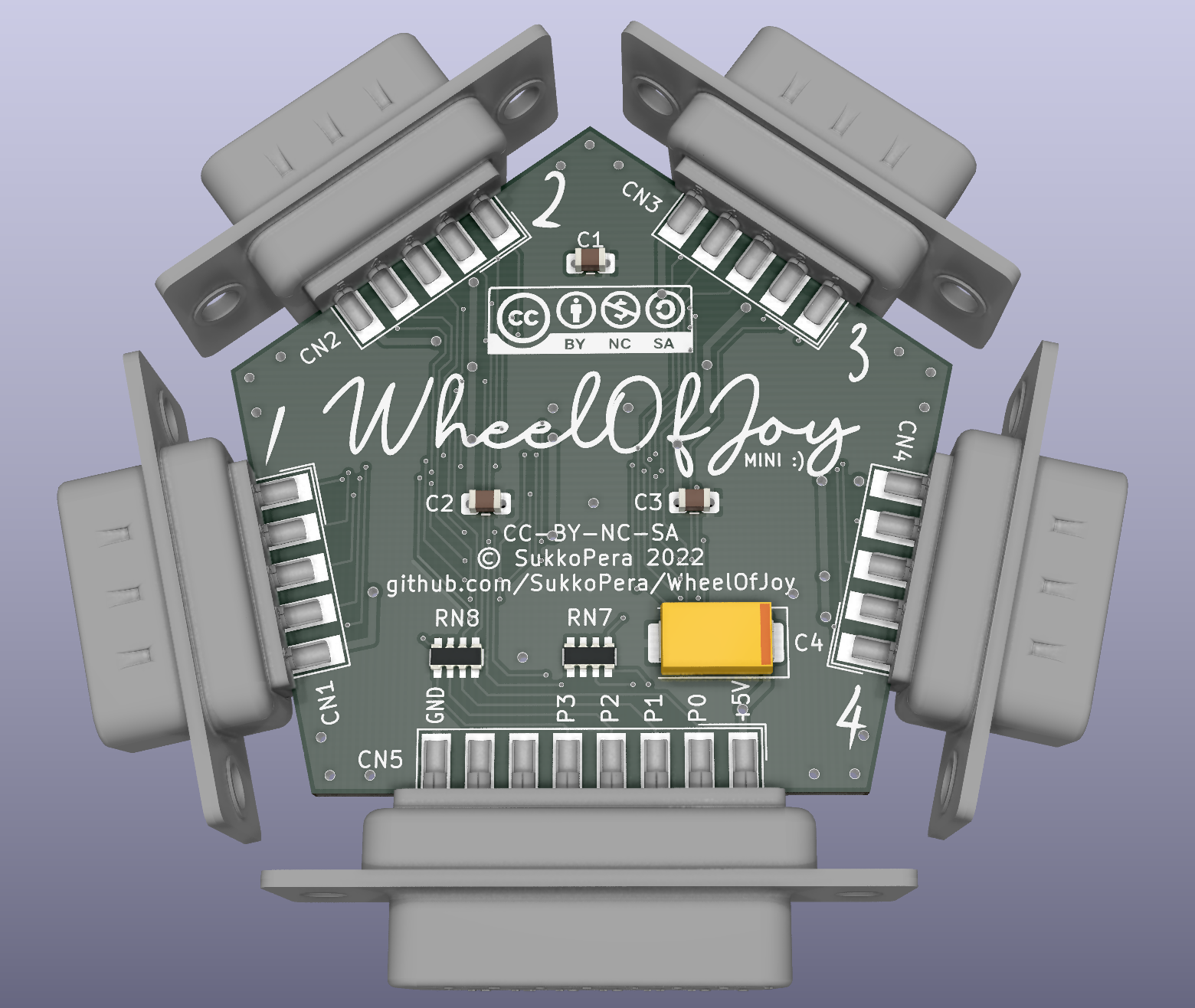
After I released WheelOfJoy, some people suggested that a 4-player adapter with support for 2 joystick buttons would probably be more useful, so here we go :).
Just like its bigger brother, the board plugs in the User Port, which means that in order to use it on a C16 or C116, you will need a User Port card.
I recommend soldering all the resistor arrays first, then the chips and the capacitors, with the ports last.
The adapter can be connected to the computer through a cable with a User Port connector on one side and a male DB-15 on the other. I did this so that the adapter can be placed more freely on the table so that all players can reach it comfortably. The adapter-end of the cable can also be soldered directly to it, if you prefer. Pin names are noted on the board, but here's a handy table:
| DB-15 Pin # | Signal | User Port Pin # | Notes |
|---|---|---|---|
| 1 | +5V | 2 | |
| 2 | P0 | B | |
| 3 | P1 | K | |
| 4 | P2 | 4 | |
| 5 | P3 | 5 | |
| 6 | /RESET | 3 | Not used by this board |
| 7 | +9V | 10 | Not used by this board |
| 8 | GND | 1, 12, A or N | |
| 9 | +5V | 2 | |
| 10 | P4 | 6 | |
| 11 | P5 | 7 | |
| 12 | P6 | J | |
| 13 | P7 | F | |
| 14 | -9V | 11 | Not used by this board |
| 15 | GND | 1, 12, A or N |
This is exactly the same cable used by WheelOfJoy.
This and these will help you make a good-looking job with your cable.
I estimate all the components required to self-build this thing to cost < 10€, probably closer to 5€ if you get them from China.
Of course there isn't any software support for this at the moment. It's up to the developers to write party games for the C16/+4 for up to 6 players!
The board uses 3 dual 4-to-1 multiplexers, totalling to 6 multiplexers: one per direction plus one for every fire button. Channel selection happens in parallel on all multiplexers and is done with the 2 high bits of the User Port.
Write a value N at the User Port register depending on the port you want to read. General formula for port P ∈ [1,4] is the following:
N = ((P - 1) << 6) | 0x3F
Or just pick your value from the following table:
| # | Binary | Hex | Dec |
|---|---|---|---|
| 1 | 00 111111 | 3F | 63 |
| 2 | 01 111111 | 7F | 127 |
| 3 | 10 111111 | BF | 191 |
| 4 | 11 111111 | FF | 255 |
Read the value of the User Port register, the lower 6 bits will report direction/button status:
| Bit 7 | Bit 6 | Bit 5 | Bit 4 | Bit 3 | Bit 2 | Bit 1 | Bit 0 |
|---|---|---|---|---|---|---|---|
| X | X | Button 2 | Button 1 | Left | Right | Down | Up |
Every bit will be 0 if the corresponding direction/button is pressed, 1 otherwise.
Any Atari-compliant joystick or joypad should work with this board. Button 2 is expected to be wired to pin 9 and to be active-low as all the other buttons. This is the most common setup, used by all 2-button joysticks and adapters designed for the Amiga, including my PSX adapter and the my variant of the Unijoysticle2.
Sega controllers also use the same configuration: you can use Master System and Mega Drive/Genesis - buttons B and C - controllers straight away as the adapter also provides power to pin 5.
The latter also means that you MUST NOT use the adapter with anything that can pull pin 5 straight to ground, such as 3-button Amiga mice (what would be the purpose of that anyway?).
Note that the few 2-button games for the C64 typically use inverted logic for button 2 (don't ask me why but this dates back to the C64 GS, I think), even if this was handled in SW, I cannot guarantee that any joysticks made this way will work correctly with the adapter.
Also keep in mind that the User Port is only guaranteed to provide 100 mA on the +5V pin, even though I don't think there's anything actually limiting that.
If you want to get this board produced, you are recommended to get the latest release rather than the current git version, as the latter might be under development and is not guaranteed to be working.
Every release is accompanied by its Bill Of Materials (BOM) file and any relevant notes about it, which you are recommended to read carefully.
The WheelOfJoyMini documentation, including the design itself, is copyright © SukkoPera 2019-2021 and is licensed under the Creative Commons Attribution-NonCommercial-ShareAlike 4.0 International License.
This documentation is distributed as is and WITHOUT ANY EXPRESS OR IMPLIED WARRANTIES whatsoever with respect to its functionality, operability or use, including, without limitation, any implied warranties OF MERCHANTABILITY, SATISFACTORY QUALITY, FITNESS FOR A PARTICULAR PURPOSE or infringement. We expressly disclaim any liability whatsoever for any direct, indirect, consequential, incidental or special damages, including, without limitation, lost revenues, lost profits, losses resulting from business interruption or loss of data, regardless of the form of action or legal theory under which the liability may be asserted, even if advised of the possibility or likelihood of such damages.
If you want to get some boards manufactured, you can get them from PCBWay through this link:

You get my gratitude and cheap, professionally-made and good quality PCBs, I get some credit that will help with this and other projects. You won't even have to worry about the various PCB options, it's all pre-configured for you!
Also, if you still have to register, you can use this link to get some bonus initial credit (and yield me some more).
You can also buy me a coffee if you want:

| Qty | Value | Footprint | References |
|---|---|---|---|
| 6 | 4.7k | Resistor_SMD:R_Array_Convex_4x0603 | RN1, RN2, RN3, RN4, RN5, RN6 |
| 3 | 100n | Capacitor_SMD:C_0805_2012Metric_Pad1.18x1.45mm_HandSolder | C1, C2, C3 |
| 3 | 74LS153 | Package_SO:SOIC-16_3.9x9.9mm_P1.27mm | U1, U2, U3 |
| 2 | 100 | Resistor_SMD:R_Array_Convex_4x0603 | RN7, RN8 |
| 1 | 100u | Capacitor_Tantalum_SMD:CP_EIA-7343-30_AVX-N_Pad2.25x2.55mm_HandSolder | C4 |
| 1 | DB15F | Connector_Dsub:DSUB-15_Female_EdgeMount_P2.77mm | CN5 |
| 1 | JOY1 | Connector_Dsub:DSUB-9_Male_EdgeMount_P2.77mm | CN1 |
| 1 | JOY2 | Connector_Dsub:DSUB-9_Male_EdgeMount_P2.77mm | CN2 |
| 1 | JOY3 | Connector_Dsub:DSUB-9_Male_EdgeMount_P2.77mm | CN3 |
| 1 | JOY4 | Connector_Dsub:DSUB-9_Male_EdgeMount_P2.77mm | CN4 |
| 1 | LOGO | WheelOfJoy:logo | V0 |
| 1 | OSHW_LOGO | WheelOfJoy:cc_by_nc_sa | V1 |
| 1 | PORT1_NO | WheelOfJoy:port1 | V2 |
| 1 | PORT2_NO | WheelOfJoy:port2 | V3 |
| 1 | PORT3_NO | WheelOfJoy:port3 | V4 |
| 1 | PORT4_NO | WheelOfJoy:port4 | V5 |
It measures 47.8 × 45.4 mm and has 2 copper layers, 1.6 mm thick.
26 parts, built around the 74LS153DC. The full list of its parts is on this page, with links to each part's symbol and footprint where PCBKit's library has them.
From the SukkoPera/WheelOfJoyMini repository on GitHub, at the commit this page was made from: the board is WheelOfJoy.kicad_pcb. PCBKit opens the board in the browser, with nothing to install.
Its repository states no licence, so its author keeps all rights: ask SukkoPera before reusing the design.
RetroStack/TRS-80-Model-I-G-E1
Hardware Replica of the TRS-80 Model I Revision G

hkzlab/ISA_EGA_CHIPS
This board is and EGA clone based on a reversed PA-WTEGA card, based on the chipset by CHIPS (P82C435 + P82A436).

fortinsylvain/MyCpu
Home brew CPU Hardware with 1-bit ALU implementation using 74LSxx, a micro-code and assembler coded in C#.

reinauer/Amiga-Boot-Selector
This is a Floppy Switcher for the Amiga 500/2000. It allows you to switch DF0/DF1, making it possible to boot from either a Gotek drive or the internal floppy drive. without relying on AmigaOS.

clemarfolly/Microdigital-TK2000
Reprodução da PCB do TK-2000 da Microdigital, clone do Micro-Professor MPF-II


djtersteegc/Tandy-Color-Computer-Multi-Pak
Respin of the Tandy 26-3024 Multi-Pak (MPI) for the DIY builder.
