2 layers40 × 20 mm

 SukkoPera/Plus4i82551
Intel 8255 Interface for the Commodore 16, 116 and Plus/4
Plus4i8255 is an open-source printed circuit board by SukkoPera, from the SukkoPera/Plus4i8255 repository on GitHub. It is a 2-layer board of 52.1 × 70 mm with 13 parts on 74 nets, routed with 444 tracks and 27 vias.
Its parts include 3 capacitors, 2 ICs and 2 connectors. It belongs with the retro computing and games boards of this library.
Plus4i8255 is an Intel 8255 Interface for the Commodore 16, 116 and Plus/4.
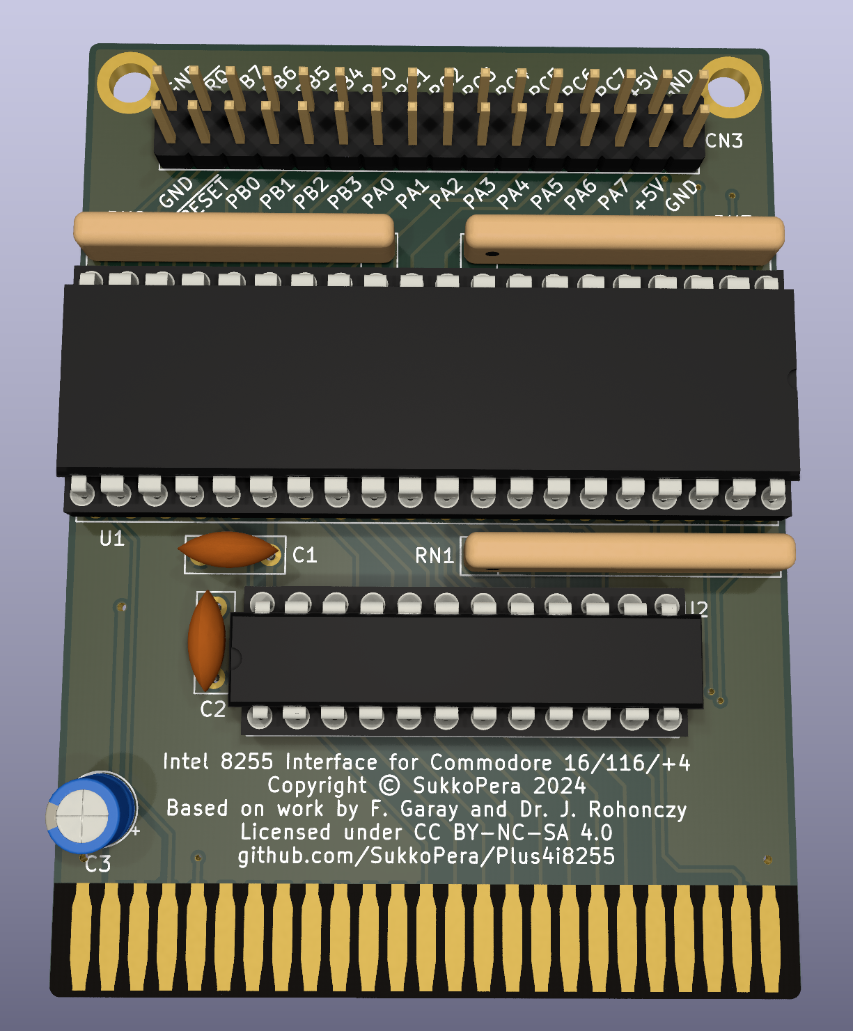
The Intel 8255 is a general purpose programmable I/O device featuring 24 I/O pins which may be individually programmed in 2 groups of 12 and used in 3 major modes of operation.
Plus4i8255 is based on the article published in Rádiótechnika 1988/12 by Ferenc Garay and Dr. János Rohonczy with a few improvements: the board has been made much smaller, the ICs doing address decoding have been turned into a GAL for easy reconfigurability (both GAL20 and GAL22 are supported) and pull-up resistors have been added on all inputs.
Intel 8255 chips can all be bought supercheap on AliExpress & similar sites. There are only a couple of other components, making this board very affordable to build for everyone.
The board is generic and can be used for a multitude of purposes, but its most common usage back in the day was to connect a 1541 drive in a parallel fashion, making it faster when used with software such as Port-Turbo V1 or Port-Backup.
A simple program to test all the board I/O pins (in Mode 1) can be found in the Release area.
The 8255 is a relatively complex chip with 3 different modes of operation. The datasheet is your friend, those for a few different chips are provided in the doc directory. Make sure to pick the one corresponding to your target chip and read it carefully.
The board exposes the four 8255 registers at $FE00-$FE03:
| Address | Description |
|---|---|
| $FE00 | Port A Register |
| $FE01 | Port B Register |
| $FE02 | Port C Register |
| $FE03 | Control Register |
Note that, while on some modern chip all registers can be read and written to, for compatibility's sake you should assume that the Control Register can only be written to, as is the case with most (older) 8255 chips.
If you want to get this board produced, you are recommended to get the latest release rather than the current git version, as the latter might be under development and is not guaranteed to be working.
Every release is accompanied by its Bill Of Materials (BOM) file and any relevant notes about it, which you are recommended to read carefully.
The Plus4i8255 documentation, including the design itself, is copyright © SukkoPera 2024 and is licensed under the Creative Commons Attribution-NonCommercial-ShareAlike 4.0 International License.
This documentation is distributed as is and WITHOUT ANY EXPRESS OR IMPLIED WARRANTIES whatsoever with respect to its functionality, operability or use, including, without limitation, any implied warranties OF MERCHANTABILITY, SATISFACTORY QUALITY, FITNESS FOR A PARTICULAR PURPOSE or infringement. We expressly disclaim any liability whatsoever for any direct, indirect, consequential, incidental or special damages, including, without limitation, lost revenues, lost profits, losses resulting from business interruption or loss of data, regardless of the form of action or legal theory under which the liability may be asserted, even if advised of the possibility or likelihood of such damages.
If you want to get some boards manufactured, you can get them from PCBWay through this link:

You get my gratitude and cheap, professionally-made and good quality PCBs, I get some credit that will help with this and other projects. You won't even have to worry about the various PCB options, it's all pre-configured for you!
Also, if you still have to register, you can use this link to get some bonus initial credit (and yield me some more).
You can also buy me a coffee if you want:

| Qty | Value | Footprint | References |
|---|---|---|---|
| 3 | 10k | Resistor_THT:R_Array_SIP9 | RN1, RN2, RN3 |
| 2 | 100n | Capacitor_THT:C_Disc_D7.0mm_W2.5mm_P5.00mm | C1, C2 |
| 2 | SCREW HOLE | MountingHole:MountingHole_3.2mm_M3_Pad | H1, H2 |
| 1 | 47u | Capacitor_THT:CP_Radial_D5.0mm_P2.00mm | C3 |
| 1 | 8255 | Package_DIP:DIP-40_W15.24mm_Socket_LongPads | U1 |
| 1 | EXPANSION_PORT | Plus4i8255:C16_Cart_Conn | CN1 |
| 1 | GAL20V8 | Package_DIP:DIP-24_W7.62mm_Socket_LongPads | U2 |
| 1 | LICENSE | Plus4i8255:cc_by_nc_sa | V0 |
| 1 | PIN_HEADER_32PIN | Connector_PinHeader_2.54mm:PinHeader_2x16_P2.54mm_Vertical | CN3 |
It measures 52.1 × 70 mm and has 2 copper layers, 1.6 mm thick.
13 parts. The full list of its parts is on this page, with links to each part's symbol and footprint where PCBKit's library has them.
From the SukkoPera/Plus4i8255 repository on GitHub, at the commit this page was made from: the board is Plus4i8255.kicad_pcb and its schematic Plus4i8255.kicad_sch. PCBKit opens the board in the browser, with nothing to install.
Its repository states no licence, so its author keeps all rights: ask SukkoPera before reusing the design.


samyk/magspoof
A portable device that can spoof/emulate any magnetic stripe, credit card or hotel card "wirelessly", even on standard magstripe (non-NFC/RFID) readers.

fossasia/pslab-scripts
Pocket Science Lab - Scripts for Sensor Experiments


willem-pennings/balancing-cube
A cube that balances itself in a corner or edge using reaction wheels

VoronDesign/Voron-Hardware
Cool Hardware designed by the Voron Design group

hoglet67/RGBtoHDMI
Bare-metal Raspberry Pi project that provides pixel-perfect sampling of Retro Computer RGB/YUV video and conversion to HDMI