2 layers57 × 55.2 mm
LogicAnalyzer
gusmanb/logicanalyzer
24 channel, 100Msps logic analyzer hardware and software
10 parts5.1kGPL-3.0

 SukkoPera/OpenRomSwitcher17
Use bigger EPROMs to replace smaller ones with switchable images
OpenRomSwitcher is an open-source printed circuit board by SukkoPera, from the SukkoPera/OpenRomSwitcher repository on GitHub. It is a 2-layer board of 19.6 × 43.2 mm with 10 parts on 31 nets, routed with 125 tracks and 8 vias.
Its parts include 6 resistors, 2 ICs and 1 connector.
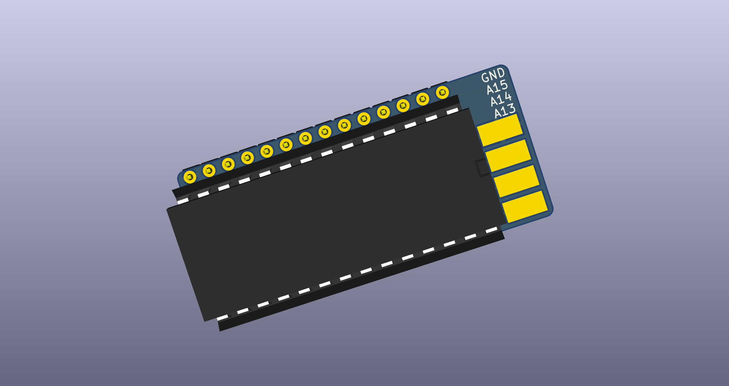
OpenRomSwitcher is an Open Hardware adapter PCB that allows the use of a 27xxx EPROM in place of a smaller (E)PROM. This is useful, for instance, for replacing the KERNAL and other ROMs in Commodore 16 home computers.
When installing JiffyDOS on a Commodore 16, you might want to retain the ability of switching to the original KERNAL ROM. The C16 ROM pinout is the same as a 27128 EPROM, so you can use a 27256 and put both the JiffyDOS and the original KERNAL on it. To you switch between them, you will need to either connect the A14 pin to VCC or GND.
OpenRomSwitcher comes as an adapter PCB that sits inbetween the original socket and the new chip and carries the A13-A15 pins out to solder pads where switches can be wired to allow the selection of a particular ROM.
Care is needed to select the proper values and placement of the resistors. You will have to choose on your own, depending on the EPROM, number of switches and exact pin connection of the original socket. Only one resistor must be soldered for each of the A13-A15 pins, either in the Switch or Straight position. This means you will ALWAYS need EXACTLY 3 resistors:
OpenRomSwitcher has been kept as small as pratically possible, and thus it can usually be installed in the original ROM socket, with no need to desolder it.
To switch between ROMs, you will need one or more switches. Every switch must connect one of the A13-A15 pads to ground when enabled. A ground pad is available on the board, but any ground spot on the original board can be used as well, if easier to reach. Since having more than switch can be cumbersome, a rotary switch can be used as well.
IMPORTANT: ALWAYS TURN YOUR DEVICE OFF BEFORE MOVING THE ROM SELECTION SWITCH(ES).
Reconsidering the initial example of a 27256 EEPROM in the C16, I would use the following resistors:
With this configuration a switch on the A14 pad that will allow switching between the ROMs.
OpenRomSwitcher is Open Hardware.
The following links were useful during the development of this project:
| Qty | Value | Footprint | References |
|---|---|---|---|
| 3 | 0R | Resistors_SMD:R_0805_HandSoldering | R4, R5, R6 |
| 3 | 10k | Resistors_SMD:R_0805_HandSoldering | R1, R2, R3 |
| 1 | CONN_01X04 | OpenRomSwitcher:LoosePads-4 | J1 |
| 1 | LOGO | w_logo:Logo_copper_OSHW_6x6mm | G*** |
| 1 | PLUG | OpenRomSwitcher:DIP-28_W15.24mm-NoSilkS | U1 |
| 1 | SOCKET | OpenRomSwitcher:DIP-28_W15.24mm-Notch | U2 |
It measures 19.6 × 43.2 mm and has 2 copper layers, 1.6 mm thick.
10 parts. The full list of its parts is on this page, with links to each part's symbol and footprint where PCBKit's library has them.
From the SukkoPera/OpenRomSwitcher repository on GitHub, at the commit this page was made from: the board is OpenRomSwitcher.kicad_pcb. PCBKit opens the board in the browser, with nothing to install.
Its repository states no licence, so its author keeps all rights: ask SukkoPera before reusing the design.
gusmanb/logicanalyzer
24 channel, 100Msps logic analyzer hardware and software

byrantech/laptop
anyon_e, a highly integrated, high end, open source laptop. Attempt the impossible.

joeycastillo/Sensor-Watch
A board replacement for the classic Casio F-91W wristwatch


OLIMEX/OLINUXINO
OLINUXINO is Open Source / Open Hardware, low cost from EUR 24 Linux Industrial grade Single Board Computer capable to operate -25+85C

rusefi/rusefi
rusefi - GPL internal combustion engine control unit

VoronDesign/Voron-Hardware
Cool Hardware designed by the Voron Design group

hoglet67/RGBtoHDMI
Bare-metal Raspberry Pi project that provides pixel-perfect sampling of Retro Computer RGB/YUV video and conversion to HDMI