2 layers
Nrf bga
github-linguist/linguist
Language Savant. If your repository's language is being reported incorrectly, send us a pull request!
12 parts14kMIT

 SukkoPera/OpenKickstartSwitcherCDTV7
Open Hardware Kickstart Switcher for the Commodore CDTV
OpenKickstartSwitcher is an open-source printed circuit board by SukkoPera, from the SukkoPera/OpenKickstartSwitcherCDTV repository on GitHub. It is a 2-layer board of 25.7 × 76.6 mm with 12 parts on 45 nets, routed with 302 tracks and 57 vias.
Its parts include 4 connectors, 3 ICs, 2 resistors and 1 capacitor. It belongs with the retro computing and games boards of this library.
OpenKickstartSwitcherCDTV is an Open Hardware Kickstart Switcher for the Commodore CDTV.
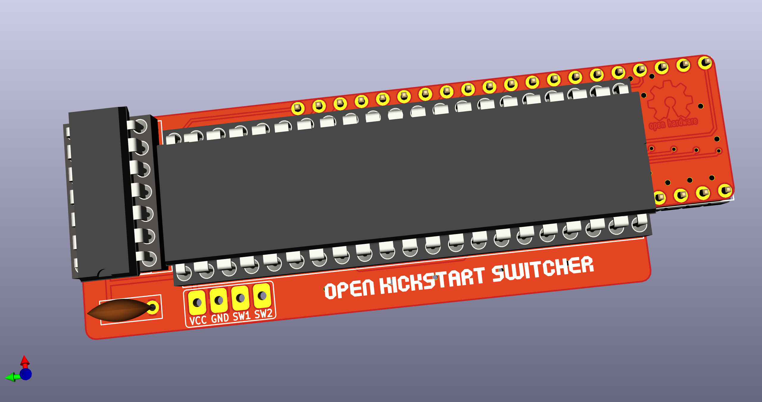
OpenKickstartSwitcherCDTV is a Kickstart switcher for the Commodore CDTV Entertainment System, based on work by Henryk Richter. It is basically the same circuit/board as OpenKickstartSwitcher but tailored in shape to the CDTV.
It allows switching among three or six different Kickstart images stored in an EPROM. The switching can be done through physical switches or by pressing the mouse/joystick buttons at power-up. The latter requires an external add-on board that is another project of mine.
Solder all components to the board. Starting with the smaller components might be a good idea, and make sure to solder the pin headers and resistor arrays before the socket. When soldering the resistor arrays, don't push them fully through the holes, as you will need to bend them against the board. No particular order is recommended for the remaining components.
The value of the two single resistors is not critical, 10k is recommended but probably any value between 5k and 50k will do.
My tests show that an SN74HC00 gate works fine. I don't recommend using parts from the HC series though, HCT or LS should be preferred.
The two resistor arrays are not always needed. You might get away without them, depending on the particular EPROM you are using: I have several EPROMs of the same model (but different production batches), and some need the resistors while others don't, so the only way to find out is actual testing. If you decide to install them, they must be of the bussed type and the recommended value is 4.7k. Be aware that these parts are polarized and must be installed with the right orientation!
The adapter can be used with either 27C800 or 27C160 EPROMs. I recommend using -100F1 EPROMs by ST, but access time is not critical: use 100ns or faster EPROMs if you can, but anything up to 150ns should work reliably.
With a 27C800 EPROM, the adapter supports 2x256 KB Kickstart images (i.e.: up to version 1.3) and 1x512 KB image (version 2 and later).
To switch between ROMs, you will need two SPDT switches, connected to the SW1/SW2 pads and ground. A ground pad is available on the board, but any ground spot on the mainboard can be used as well, if easier to reach.
| ROM Image # | Size (KB) | SW1 | SW2 |
|---|---|---|---|
| 1 | 256 | LOW | LOW |
| 2 | 256 | HIGH | LOW |
| 3 | 512 | x | HIGH |
(x = Don't Care)
So, basically:
You can also use a single ON-OFF-ON DPDT switch, just wire ground to the middle pins, SW1 and SW2 on one side and SW2 on the other.
As SW1/SW2 will both read as HIGH if left unconnected, the 512 KB Kickstart will be selected if no switches are wired.
You can fully ignore the A19 pad on the bottom side of the board, when using a 27C800 EPROM.
With a 27C160 EPROM, the adapter supports up to 4x256 KB Kickstart images and 2x512 KB images.
You will need to solder an additional switch to the A19 pad on the bottom side of the board. VCC and GND pads are provided nearby so that you can also solder a pull-up/down resistor.
| ROM Image # | Size (KB) | SW1 | SW2 | A19 |
|---|---|---|---|---|
| 1 | 256 | LOW | LOW | LOW |
| 2 | 256 | HIGH | LOW | LOW |
| 3 | 512 | x | HIGH | LOW |
| 4 | 256 | LOW | LOW | HIGH |
| 5 | 256 | HIGH | LOW | HIGH |
| 6 | 512 | x | HIGH | HIGH |
IMPORTANT: ALWAYS TURN YOUR CDTV OFF BEFORE MOVING THE SELECTION SWITCHES.
When flashing the EPROM, make sure that the ROM images you are using are exactly 262144 or 524288 bytes long, and just concatenate them. Take care to use the correct byte ordering, as the Amiga hardware expects 16-bit words to be stored in the big-endian format (which is NOT the format UAE expects them in, for the record). On Unix-like systems you can use the conv=swab option of dd to change the byte ordering.
27C800s and 27C160 are 42-pin EPROMs and most programmers only support chips up to 40 pins. This is the case with the popular TL866 programmer, for instance. You can get around this limitation with an adapter PCB. There are at least two open designs of such an adapter:
I have only used the latter and found it to be working fine.
Once your OpenKickstartSwitcherCDTV is assembled and programmed, the rest of the installation should be pretty straightforward:
Of course, if you use OpenAmigaMouseTrigger there is no need to drill any holes.
The excellent DiagROM by chucky can be used with OpenKickstartSwitcherCDTV, even though not all functions work on a CDTV.
Normally it is distributed as a 512 KB image, but most of the space is unused, so I have created a 256 KB version of DiagROM 1.0 by simply truncating the image. It is NOT GUARANTEED TO WORK, but it looks fine to me. It can be downloaded here.
The OpenKickstartSwitcherCDTV documentation, including the design itself, is copyright © SukkoPera 2018-2019.
OpenKickstartSwitcherCDTV is Open Hardware licensed under the CERN OHL v. 1.2.
You may redistribute and modify this documentation under the terms of the CERN OHL v.1.2. This documentation is distributed as is and WITHOUT ANY EXPRESS OR IMPLIED WARRANTIES whatsoever with respect to its functionality, operability or use, including, without limitation, any implied warranties OF MERCHANTABILITY, SATISFACTORY QUALITY, FITNESS FOR A PARTICULAR PURPOSE or infringement. We expressly disclaim any liability whatsoever for any direct, indirect, consequential, incidental or special damages, including, without limitation, lost revenues, lost profits, losses resulting from business interruption or loss of data, regardless of the form of action or legal theory under which the liability may be asserted, even if advised of the possibility or likelihood of such damages.
A copy of the full license is included in file LICENSE.pdf, please refer to it for applicable conditions. In order to properly deal with its terms, please see file LICENSE_HOWTO.pdf.
The contact points for information about manufactured Products (see section 4.2) are listed in file PRODUCT.md.
Any modifications made by Licensees (see section 3.4.b) shall be recorded in file CHANGES.md.
The Documentation Location of the original project is https://github.com/SukkoPera/OpenKickstartSwitcherCDTV/.
Since the project is open you are free to get the PCBs made by your preferred manufacturer, however in case you want to support the development, you can order them from PCBWay through this link:

You get cheap, professionally-made and good quality PCBs, I get some credit that will help with this and other projects. You won't even have to worry about the various PCB options, it's all pre-configured for you!
Also, if you still have to register to that site, you can use this link to get some bonus initial credit (and yield me some more).
Again, if you want to use another manufacturer, feel free to, don't feel obligated :). But then you can buy me a coffee if you want:

If you need help or have questions, you can join the official Telegram group.
Thanks to Henryk Richter, Aldo PRS and screwbreaker.
| Qty | Value | Footprint | References |
|---|---|---|---|
| 2 | 10k | Resistor_THT:R_Axial_DIN0204_L3.6mm_D1.6mm_P7.62mm_Horizontal | R1, R2 |
| 2 | 9x4k7 | OpenKickstartSwitcher:R_Array_SIP10_OnSide | RN1, RN2 |
| 1 | 100n | Capacitor_THT:C_Disc_D7.0mm_W2.5mm_P5.00mm | C1 |
| 1 | 7400 | Package_DIP:DIP-14_W7.62mm_Socket | U3 |
| 1 | Conn_01x03 | OpenKickstartSwitcher:SolderJumper | J4 |
| 1 | Conn_01x04 | OpenKickstartSwitcher:Solderable_PinHeader_1x04 | J2 |
| 1 | KS_SOCKET | OpenKickstartSwitcher:DIP-40_DualHeaderStrips | U1 |
| 1 | LOGO | logo:logo | J98 |
| 1 | M27C800 | OpenKickstartSwitcher:DIP-42_Socket | U2 |
| 1 | OSHW_LOGO | w_logo:Logo_copper_OSHW_6x6mm | J99 |
It measures 25.7 × 76.6 mm and has 2 copper layers, 1.6 mm thick.
12 parts. The full list of its parts is on this page, with links to each part's symbol and footprint where PCBKit's library has them.
From the SukkoPera/OpenKickstartSwitcherCDTV repository on GitHub, at the commit this page was made from: the board is OpenKickstartSwitcher.kicad_pcb. PCBKit opens the board in the browser, with nothing to install.
Its repository states no licence, so its author keeps all rights: ask SukkoPera before reusing the design.
github-linguist/linguist
Language Savant. If your repository's language is being reported incorrectly, send us a pull request!


google/mozc-devices
Circuit diagrams and firmware source code for Gboard DIY keyboards


hackclub/OnBoard
💡 Join 1,000 teenagers and make your first PCB with a $100 grant!

VoronDesign/Voron-Tap
Tap is a nozzle-based z-probe for the V2 and Trident printer designs. The entire toolhead moves to trigger an optical switch. Tap offers many advantages:

stacksmashing/pico-tpmsniffer
A simple, very experimental TPM sniffer for LPC bus