
2 layers327.9 × 139 mm
Coco2
baldengineer/bit-preserve
Project for capturing vintage, classic, aka old computer schematics in KiCad.
147 parts446

 Sudo-Aju/SpiderBlink1
A blinky board but is shape of a spiderweb
Spider is an open-source printed circuit board by Sudo-Aju, from the Sudo-Aju/SpiderBlink repository on GitHub. It is a 2-layer board of 39.6 × 41.4 mm with 20 parts on 19 nets, routed with 227 tracks and 21 vias.
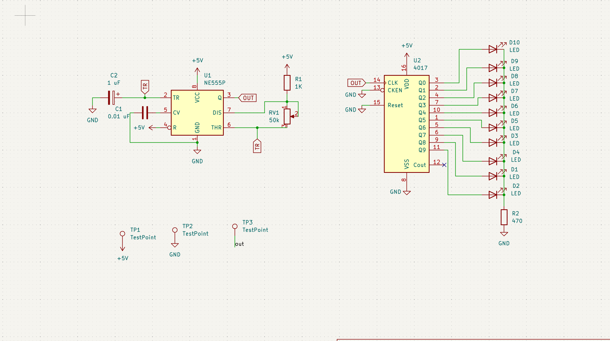
It is built around the NE555P. Its parts include 10 diodes, 2 capacitors, 2 resistors and 2 ICs.

A Tiny LED Blinker in Shape of a Spiderweb



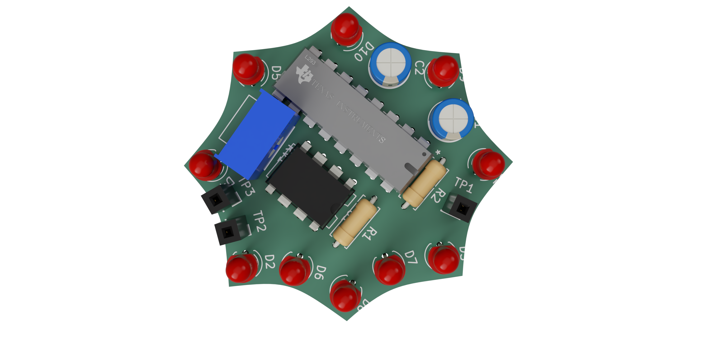
SpiderBlink is a 555 LED chaser board that blinks 10 LEDs in a variable speed sequence using a NE555P timer IC and a CD4017 decade counter. I built this as a beginner PCB project to learn schematic design, PCB routing, and hands-on soldering.
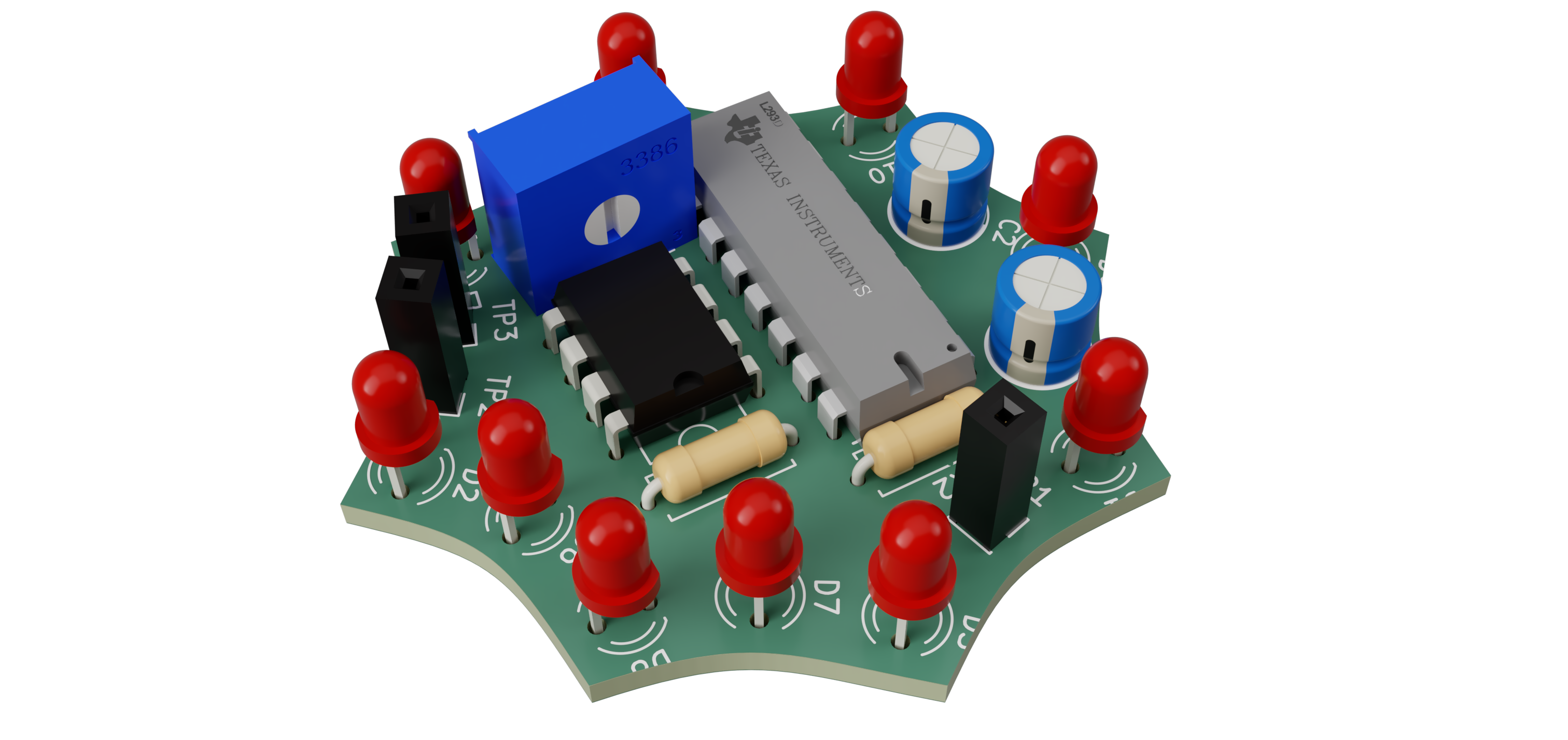
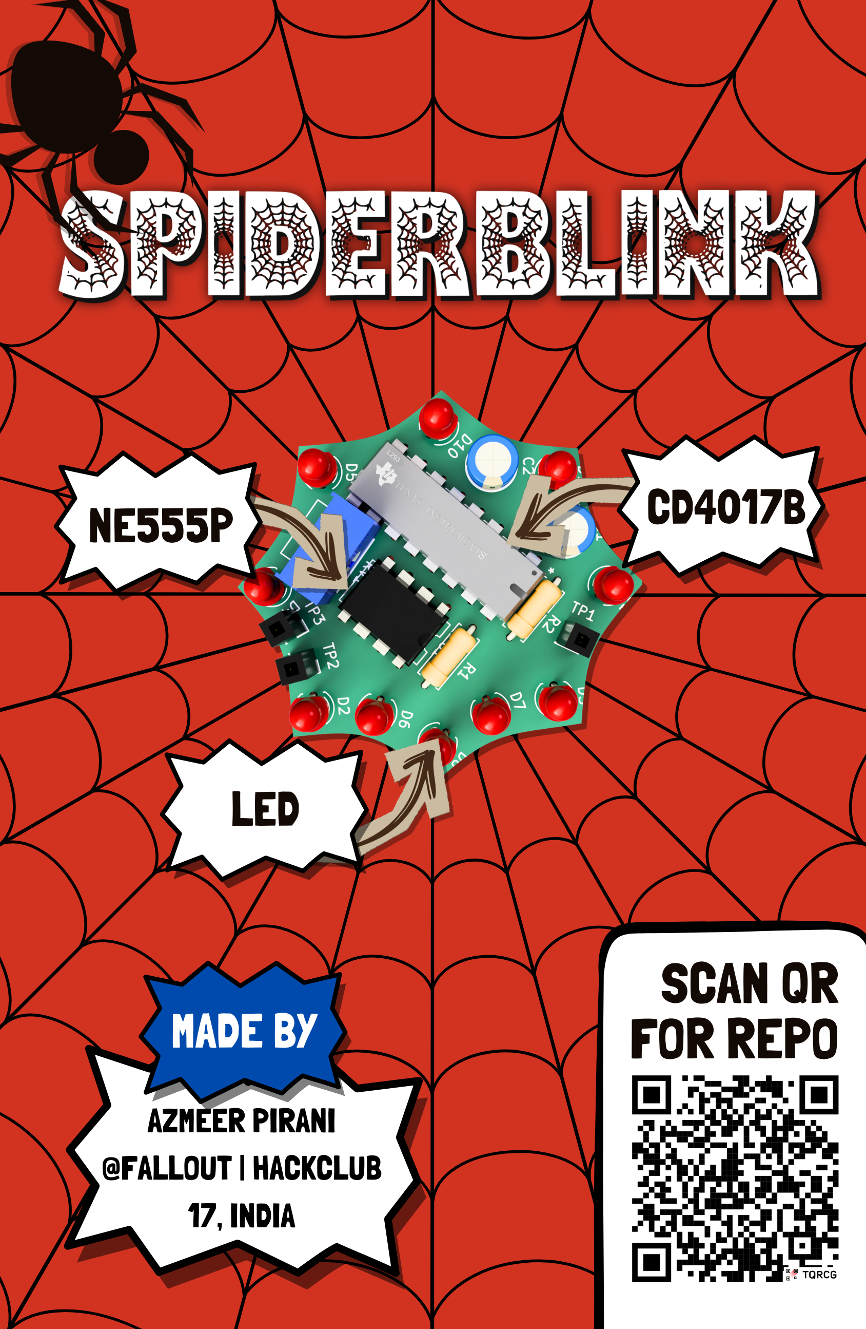
I wanted to dvelve deeper into embedded electronics, so thought this might be the chance for me to understand more about ICs, Timers and Oscillators
| Reference | Description | Manufacturer | MPN | Quantity | Supplier | Unit Price (USD) | Extended Price (USD) | Product Link |
|---|---|---|---|---|---|---|---|---|
| C1 | 0.01 µF Ceramic Capacitor | Murata | GRM188R71H103KA01D | 1 | Murata | 0.10 | 0.10 | https://www.murata.com/en-global/products/productdetail?partno=GRM188R71H103KA01D |
| C2 | 1 µF Ceramic Capacitor | Murata | GRM188R60J105KA01D | 1 | Murata | 0.15 | 0.15 | https://www.murata.com/en-global/products/productdetail?partno=GRM188R60J105KA01D |
| D1-D10 | 5 mm Red LED | Kingbright | WP7113ID | 10 | Kingbright | 0.18 | 1.80 | https://www.kingbrightusa.com/product.asp?catalog_name=LED&product_id=WP7113ID |
| R1 | 1 kΩ 1/4W Through-Hole Resistor | Yageo | CFR-25JB-52-1K | 1 | Yageo | 0.02 | 0.02 | https://www.yageo.com/en/Product/Search?partNumber=CFR-25JB-52-1K |
| R2 | 470 Ω 1/4W Through-Hole Resistor | Yageo | CFR-25JB-52-470R | 1 | Yageo | 0.02 | 0.02 | https://www.yageo.com/en/Product/Search?partNumber=CFR-25JB-52-470R |
| RV1 | 50 kΩ Trimmer Potentiometer | Bourns | 3362P-1-503LF | 1 | Bourns | 1.25 | 1.25 | https://www.bourns.com/products/trimpot-trimming-potentiometers/product/3362 |
| U1 | NE555P Timer IC | Texas Instruments | NE555P | 1 | Texas Instruments | 0.60 | 0.60 | https://www.ti.com/product/NE555 |
| U2 | CD4017B Decade Counter | Texas Instruments | CD4017B | 1 | Texas Instruments | 0.75 | 0.75 | https://www.ti.com/product/CD4017B |
The PCB was designed with the reference of a piderweb, more specifically Spiderman
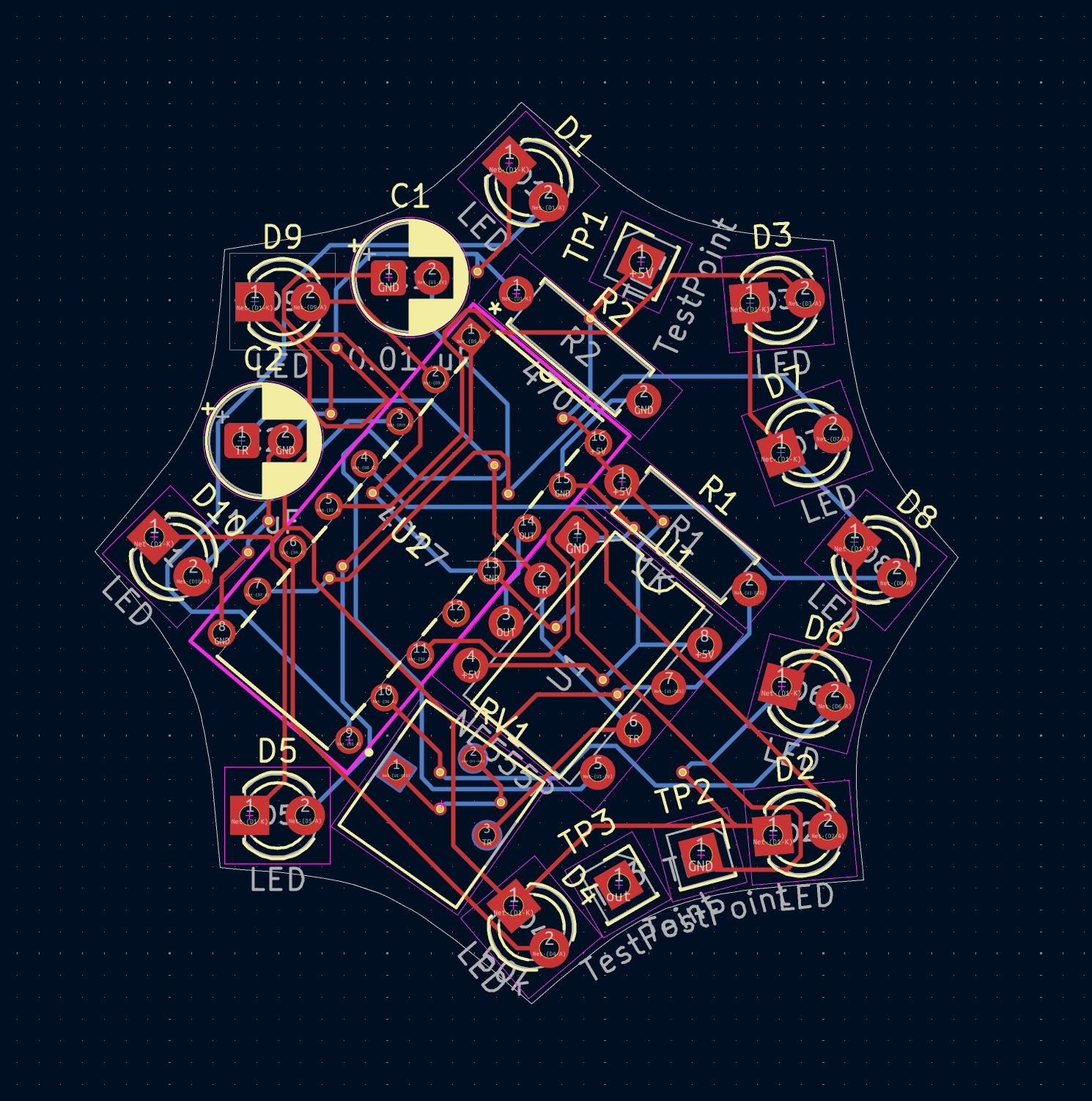
SpiderBlink/
├── PCB/
├── BOM.csv
├── Gallery/
└── README.mdNavigate to:
./PCB/Gerber.zipUpload the Gerber files to your preferred PCB manufacturer.
All required components can be found in:
./PCB/BOM.csvRecommended assembly should follow a low-profile to high-profile sequence to simplify alignment and reduce rework.
Suggested order:
Before powering:
Contributions, suggestions, and feedback are welcome.
If you'd like to improve SpiderBlink:
git clone https://github.com/Sudo-Aju/SpiderBlink.git
cd SpiderBlinkBuilt with ❤️ for:
This project is licensed under the MIT License.
| Qty | Value | Footprint | References |
|---|---|---|---|
| 10 | LED | LED_THT:LED_D3.0mm | D1, D2, D3, D4, D5, D6, D7, D8, D9, D10 |
| 3 | TestPoint | Connector_PinSocket_2.54mm:PinSocket_1x01_P2.54mm_Vertical | TP1, TP2, TP3 |
| 1 | 0.01 uF | Capacitor_THT:CP_Radial_D5.0mm_P2.00mm | C1 |
| 1 | 1 uF | Capacitor_THT:CP_Radial_D5.0mm_P2.00mm | C2 |
| 1 | 1K | Resistor_THT:R_Axial_DIN0207_L6.3mm_D2.5mm_P7.62mm_Horizontal | R1 |
| 1 | 4017 | blinky:N16 | U2 |
| 1 | 470 | Resistor_THT:R_Axial_DIN0207_L6.3mm_D2.5mm_P7.62mm_Horizontal | R2 |
| 1 | 50k | blinky:TRIM_3362P-1-102 | RV1 |
| 1 | NE555P | Package_DIP:DIP-8_W7.62mm | U1 |
It measures 39.6 × 41.4 mm and has 2 copper layers, 1.6 mm thick.
20 parts, built around the NE555P. The full list of its parts is on this page, with links to each part's symbol and footprint where PCBKit's library has them.
From the Sudo-Aju/SpiderBlink repository on GitHub, at the commit this page was made from: the board is PCB/Source/Spider.kicad_pcb and its schematic PCB/Source/Spider.kicad_sch. PCBKit opens the board in the browser, with nothing to install.
Its repository states no licence, so its author keeps all rights: ask Sudo-Aju before reusing the design.
baldengineer/bit-preserve
Project for capturing vintage, classic, aka old computer schematics in KiCad.

The-Invent0r/8-bit-Computer-PCB
These are the KiCAD files for my 8-Bit Computer.

DarcyJProjects/touchtone555
An open-source DIY, NE555-based analogue synthesizer - play notes with a stylus


benjiaomodular/SynthCard
I designed this project with the help of PCBWay. You can get a copy of these cards through the PCBWay Shared Projects page.

fortinsylvain/MyCpu
Home brew CPU Hardware with 1-bit ALU implementation using 74LSxx, a micro-code and assembler coded in C#.

hackup/C128Diag
Replica of the Commodore C128 Diagnostic Test cartridge Assy No. 325093-01.