4 layers57.1 × 33.9 mm
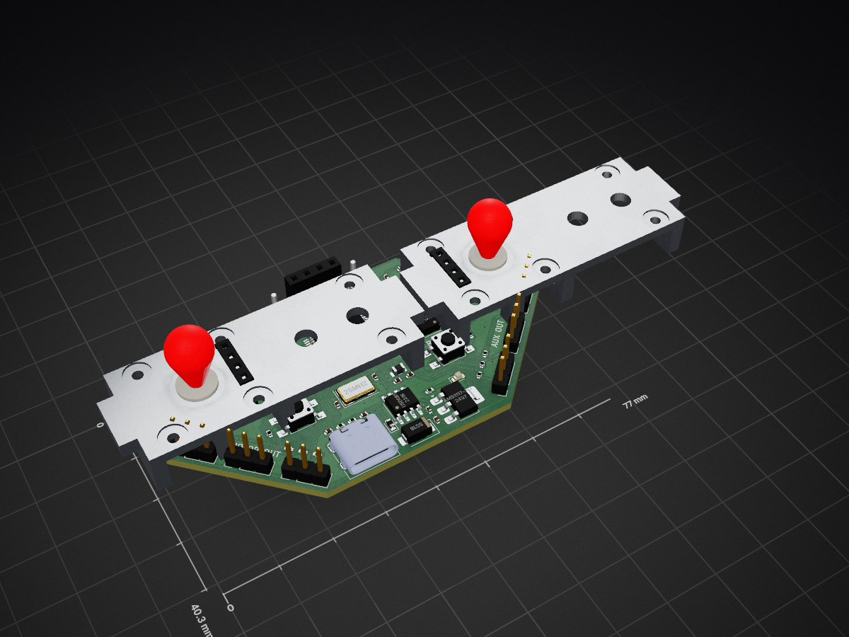
 subbumani12/flightcontroller
A compact STM32F411-based flight controller PCB designed in KiCad for multirotor UAVs and embedded flight-control applications. Integrates IMU, magnetometer, barometer, microSD, USB, UART, and multiple motor/auxiliary outputs.
Flightcontroller is an open-source printed circuit board by subbumani12, from the subbumani12/flightcontroller repository on GitHub. It is a 2-layer board of 77 × 40.3 mm with 82 parts on 92 nets, routed with 659 tracks and 59 vias.
It is built around the BMP280, LIS3MDL and AMS1117-3.3, with the AT24CS64-SSHM-B, LSM6DS3 and USB6B1 among its other parts. Its parts include 28 capacitors, 24 resistors, 11 connectors, 7 ICs and 4 diodes. It belongs with the robots and motor control boards and the STM32 boards of this library.


A custom STM32F411-based flight controller PCB designed for multirotor, UAV, robotics, and embedded flight-control applications.
The board integrates an IMU, magnetometer, barometric sensor, EEPROM, MicroSD storage, USB-C, SWD debugging, UART interfaces, and dedicated motor/auxiliary outputs on a compact 2-layer PCB designed in KiCad.
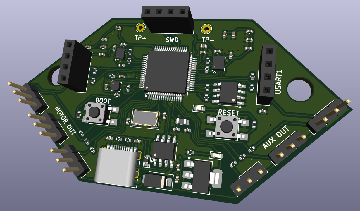
This project is a custom flight-controller hardware design centered around the STM32F411RET6 ARM Cortex-M4 microcontroller.
The STM32 handles sensor acquisition, flight-control processing, peripheral communication, data logging, and motor/auxiliary output generation.
The board combines:
The PCB was designed in KiCad, with emphasis on compact routing, sensor decoupling, accessible debugging, and organized external interfaces.
| Component | Part |
|---|---|
| Microcontroller | STM32F411RET6 |
| IMU | LSM6DS3 – 3-axis Accelerometer + 3-axis Gyroscope |
| Magnetometer | LIS3MDL – 3-axis |
| Barometer | BMP280 |
| EEPROM | AT24C256A |
| Storage | MicroSD |
| USB | USB Type-C |
| Debug | SWD |
| Serial | UART1 / UART2 |
| Motor Outputs | MOTOR1 / MOTOR2 / MOTOR3 |
| Auxiliary Outputs | AUX1 / AUX2 / AUX3 |
| Logic Supply | 3.3 V |
| PCB | 2-layer |
| EDA Tool | KiCad |
The complete hardware feature set is documented in the original design specification.
                         USB Type-C
                             │
                             ▼
                       USB Protection
                             │
                             ▼
                       Power / 3.3 V
                             │
                             ▼
                    ┌─────────────────┐
                    │   STM32F411     │
                    │   Flight MCU    │
                    └────────┬────────┘
                             │
          ┌──────────────────┼──────────────────┐
          │                  │                  │
          ▼                  ▼                  ▼
        I²C                 SPI               UART
          │                  │                  │
    ┌─────┼─────┐       ┌────┴────┐       ┌────┴────┐
    ▼     ▼     ▼       ▼         ▼       ▼         ▼
  LSM6DS3 LIS3MDL EEPROM BMP280   MicroSD  UART1    UART2
    │     │
└─────┴────── Sensor DataThe LSM6DS3 provides:
It serves as the primary inertial sensor for attitude estimation, angular-rate measurement, motion detection, and flight-control feedback.
The IMU communicates with the STM32 through I²C.
The LIS3MDL provides 3-axis magnetic-field measurements and can be used as a magnetic heading reference for navigation and orientation estimation.
It communicates through I²C and includes an interrupt connection to the MCU.
The BMP280 provides pressure measurements for:
The sensor is connected through SPI.
The onboard EEPROM provides non-volatile storage for:
A dedicated MicroSD interface provides onboard flight-data storage using SPI:
SD_SPI_MOSI
SD_SPI_MISO
SD_SPI_SCK
SD_CHIPSEL
It can be used for sensor measurements, telemetry, debugging information, controller parameters, and flight logs.
Three dedicated motor interfaces are provided:
MOTOR1_OUT
MOTOR2_OUT
MOTOR3_OUT
Each connector provides:
+5V
GND
SIGNAL
The motor-control signals are generated using STM32 timer peripherals and can interface with external ESCs or motor-control hardware.
AUX1_OUT
AUX2_OUT
AUX3_OUT
Each provides:
+5V
GND
SIGNAL
These can be used for additional actuators or flight-controller peripherals.
Two serial interfaces are exposed:
UART1_TX
UART1_RX

UART2_TX
UART2_RX
Potential applications include GPS, telemetry, radio receivers, external sensors, and configuration interfaces.
A dedicated SWD interface is provided for programming and debugging:
SWDIO
SWCLK
3.3V
GND
The board also includes test points for convenient hardware debugging.
The board uses an onboard 3.3 V regulation stage for the STM32 and peripheral electronics.
The power section includes:
The additional ferrite filtering is intended to reduce high-frequency supply noise around the MCU.
The board includes a USB Type-C interface providing:
USB ESD protection is included on the data interface.
The USB connection can be used for firmware development, communication, configuration, debugging, and powering the board during development.
Dedicated BOOT and RESET buttons are also provided for firmware programming, recovery, and MCU reset.
Designed using KiCad, the PCB focuses on compact two-layer implementation and practical hardware debugging.
        ┌─────────────┐
        │    IMU      │
        │   LSM6DS3   │
        └──────┬──────┘
               │
        ┌──────▼──────┐
        │ Magnetometer│
        │   LIS3MDL   │
        └──────┬──────┘
               │
        ┌──────▼──────┐
        │  Barometer  │
        │    BMP280   │
        └──────┬──────┘
               │
               ▼
        ┌──────────────┐
        │  STM32F411   │
        │    MCU       │
        └──────┬───────┘
               │
        ┌──────┼──────────┐
        ▼      ▼          ▼
Motors AUX TelemetryThe STM32 acquires sensor data, processes the measurements using flight-control firmware, and generates outputs for connected ESCs, motors, and auxiliary peripherals.
Possible future revisions include:
This hardware platform can be explored for:
Hardware: PCB design completed EDA: KiCad Architecture: STM32F411-based PCB: 2-layer
This project is intended for educational, research, and UAV hardware-development purposes.
This project is open-source and intended for educational, research, and UAV hardware-development purposes.
| Qty | Value | Footprint | References |
|---|---|---|---|
| 13 | 22 | Resistor_SMD:R_0402_1005Metric | R10, R11, R12, R19, R20, R21, R23, R24, R25, R27, R28, R29, R30 |
| 11 | 2.2u | Capacitor_SMD:C_0402_1005Metric | C3, C4, C5, C10, C11, C23, C24, C25, C26, C27, C28 |
| 10 | 0.1u | Capacitor_SMD:C_0402_1005Metric | C6, C7, C8, C9, C16, C17, C18, C19, C21, C22 |
| 8 | 5.1k | Resistor_SMD:R_0402_1005Metric | R4, R5, R6, R7, R8, R9, R17, R18 |
| 6 | Conn_01x03_Pin | Connector_PinHeader_2.54mm:PinHeader_1x03_P2.54mm_Vertical | J3, J4, J5, J7, J8, J9 |
| 3 | Conn_01x04_Socket | Connector_PinSocket_2.54mm:PinSocket_1x04_P2.54mm_Vertical | J11, J12, J13 |
| 2 | 10k | Resistor_SMD:R_0402_1005Metric | R2, R3 |
| 2 | 1u | Capacitor_SMD:C_0402_1005Metric | C12, C13 |
| 2 | 20p | Capacitor_SMD:C_0402_1005Metric | C14, C15 |
| 2 | 22u | Capacitor_SMD:C_0402_1005Metric | C1, C2 |
| 2 | LED | LED_SMD:LED_0603_1608Metric | D1, D5 |
| 2 | MountingHole | MountingHole:MountingHole_5mm | H1, H2 |
| 2 | SW_Push | Button_Switch_SMD:SW_SPST_TL3305A | SW1, SW2 |
| 2 | TestPoint | TestPoint:TestPoint_THTPad_D2.0mm_Drill1.0mm | TP1, TP2 |
| 1 | 1.5k | Resistor_SMD:R_0402_1005Metric | R1 |
| 1 | 100n | Capacitor_SMD:C_0402_1005Metric | C20 |
| 1 | 120R | Inductor_SMD:L_0805_2012Metric | FB1 |
| 1 | 25MHz | Crystal:Crystal_SMD_0603-4Pin_6.0x3.5mm | Y1 |
| 1 | AMS1117-3.3 | Package_TO_SOT_SMD:SOT-223-3_TabPin2 | U1 |
| 1 | AT24CS64-SSHM | Package_SO:SOIC-8_3.9x4.9mm_P1.27mm | U6 |
| 1 | BMP280 | Package_LGA:Bosch_LGA-8_2x2.5mm_P0.65mm_ClockwisePinNumbering | U4 |
| 1 | D_Schottky | Diode_SMD:D_0603_1608Metric | D3 |
| 1 | LIS3MDL | Package_LGA:LGA-12_2x2mm_P0.5mm | U5 |
| 1 | LSM6DS3 | Package_LGA:LGA-14_3x2.5mm_P0.5mm_LayoutBorder3x4y | U2 |
| 1 | Micro_SD_Card_Det1 | Connector_Card:microSD_HC_Molex_104031-0811 | J15 |
| 1 | SS18 | Diode_SMD:D_SMA | D2 |
| 1 | STM32F411RETx | Package_QFP:LQFP-64_10x10mm_P0.5mm | U3 |
| 1 | USB6B1 | Package_SO:SOIC-8_3.9x4.9mm_P1.27mm | U7 |
| 1 | USB_C_Receptacle_USB2.0_14P | Connector_USB:USB_C_Receptacle_HRO_TYPE-C-31-M-12 | J1 |
It measures 77 × 40.3 mm and has 2 copper layers, 1.6 mm thick.
82 parts, built around the BMP280, LIS3MDL, AMS1117-3.3 and AT24CS64-SSHM-B. The full list of its parts is on this page, with links to each part's symbol and footprint where PCBKit's library has them.
From the subbumani12/flightcontroller repository on GitHub, at the commit this page was made from: the board is flightcontroller.kicad_pcb and its schematic flightcontroller.kicad_sch. PCBKit opens the board in the browser, with nothing to install.
Its repository states no licence, so its author keeps all rights: ask subbumani12 before reusing the design.

Daniqnn/Proyecto_Final
Proyecto final de Mecatronica, ITLA 2026 C1. Made by José Mañón, Cesar Camacho, Henry bautista, Wilmir Calcaño y Harlin Fransisco.

ajisrawi/dronemagnav
Magnetic-anomaly navigation (MagNav) board + firmware for drones: ESP32-S3, BMI088, LIS3MDL, BMP280, u-blox GNSS, WDMAM map matching, particle filter, MAVLink, phone route planner. Proprietary - all rights reserved.

obrevskaya/quadcopter_flight_controller_pcb
Проект посвящён разработке печатной платы контроллера полёта квадрокоптера в системе автоматизированного проектирования KiCad.

PeriwalPratham/FlightController
A basic PCB design which contains all components for a solo yet affordable basic drone controller


lrodorigo/heishamon-lr-aquarea-board
A simple alternative hardware implementation for the great HeishaMon board for communicating with Panasonic heatpumps
