
2 layers164.2 × 199.4 mm
Individual mic
subashtimilsina/Sound-Source-Localization-Hardware
Hardware Part of sound source localization. Array circuit and 3 wheel omni drive code
16 partsMIT
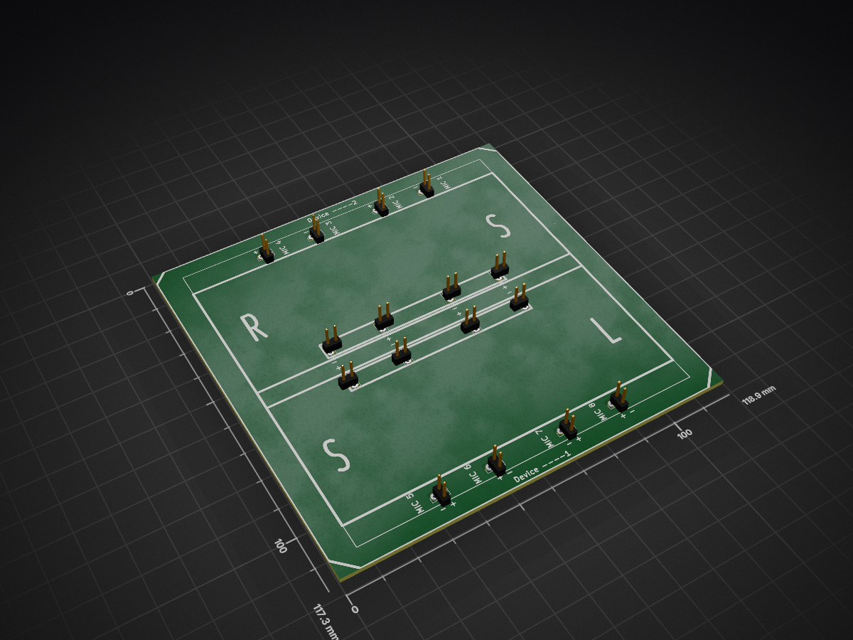
Hardware Part of sound source localization. Array circuit and 3 wheel omni drive code
Mic Array is an open-source printed circuit board by subashtimilsina, from the subashtimilsina/Sound-Source-Localization-Hardware repository on GitHub, published under the MIT licence. It is a 2-layer board with 16 parts on 16 nets, routed with 64 tracks and 0 vias.
It belongs with the audio and music boards of this library.
Hardware design files and firmware for a mobile robot used in cubical microphone-array sound-source localization. The platform combines a three omni-wheel holonomic base with an eight-channel mic harness routed through custom KiCad PCBs. Signal processing (GCC-PHAT, grid search, real-time demos, etc.) lives in the companion software repository.
Software & algorithms (SSL) · ISCRAM 2020 paper (PDF)
The robot was built to support 3D sound-source localization using a cubical array: one microphone channel is associated with each vertex of a rigid cube, so delays between channels carry direction-of-arrival information. The acquisition side (USB audio interfaces, streaming, and localization code) is described in the Sound-Source-Localization repo; this repository holds:
Experimental context and notation are given in the ISCRAM 2020 publication linked above.
Holonomic base
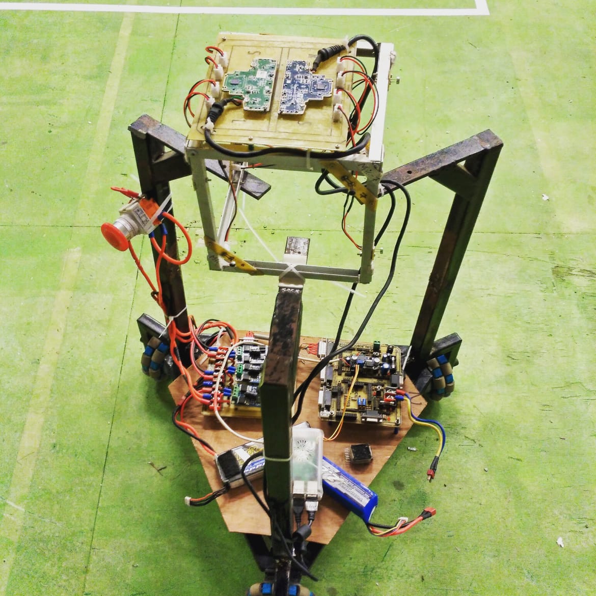
The robot stands on three omni wheels arranged for omnidirectional motion. Each wheel is driven by a DC motor with encoder/driver electronics (exact brackets and chassis cad are not stored in this repo; use the photograph and the ISCRAM paper as a reference for proportions and wiring clearance).
Cubical microphone frame
A rigid cube (or cubic frame) mounts above the base. Eight microphone capsules are placed at the corners of the cube so that pairwise time differences match the geometry used in the software (GCC-PHAT / grid search over candidate directions).
Cable routing
From each vertex, a short harness runs to a local breakout (see Individual array/), then longer runs converge on the Mic_Array controller board mounted near the compute stack. Keep pair lengths symmetric where possible and avoid running mic wires parallel to motor leads without shielding to reduce EMI.
Stack
The upper tray typically carries USB audio devices (multi-channel), power distribution, and the small-form PC or embedded computer used in the software repo’s notebooks and real-time scripts.
All boards were designed in KiCad (legacy .sch / .kicad_pcb + cache libs). For fabrication, open the .kicad_pcb in a current KiCad release, run DRC, and export Gerbers; SVGs in each folder are convenient for documentation and quick visual checks.
Individual array/ — single-channel adapter| Artifact | Purpose |
|---|---|
Individual_mic.sch / Individual_mic.kicad_pcb | One microphone MIC footprint wired to a 2-pin header and a JST EH-style 2-pin cable footprint (JST_CONN) for removable harness segments. |
Use one small circuit board per microphone site (or per edge entry point, depending on your mechanical layout) so cube wiring can be unplugged for service.
Array_Ckt/ and Controller_Mic/ — eight-channel routing| Artifact | Purpose |
|---|---|
Mic_Array.sch / Mic_Array.kicad_pcb | Consolidates eight microphone channels: connectors are labeled Mic1–Mic4 in two symmetric groups (covering all eight physical channels—see schematic nets MicN vs MicN_chip). Each channel uses two CONN_01X02 headers: one faces the harness/array side, one faces the digitizer / preamp side. |
Mic_Array-brd.svg, Mic_Array-B.Cu.svg, drawing.svg | Board artwork and copper preview for assembly notes. |
Array_Ckt/ and Controller_Mic/ are two KiCad project folders; compare Gerber outlines if you only need one physical board revision for your build.
Folder: 3_Omni_Base/
| Item | Description |
|---|---|
3_Omni_Base.atsln, 3_Omni_Base/*.cppproj | Microchip Studio (Atmel Studio) solution targeting an AVR device (16 MHz F_CPU in headers.h). |
main.cpp | Initializes a Wheel controller and runs a control loop: read command data, compute wheel speeds, update PWM to three motors. |
Wheel.cpp / Wheel.h | Holonomic mixing: 3×3 coupling matrix maps robot (vx, vy, ω)-style commands to three wheel velocities; Motor objects abstract per-wheel drive; get_joystick_data() reads UART packets (rcvdata[]), derives azimuth / elevation in preprocess_data(), and sets velocity_robot[] before calculate_wheel_velocity() and update_wheel_velocity(). |
uart.cpp / Motor.cpp | Low-level serial I/O and motor timing (MAX_RPM defined in Wheel.h). |
Debug/*.hex | Built firmware images (verify target MCU and fuse bits before flashing). |
Typical workflow: open the solution in Microchip Studio, select the correct AVR part and programmer, build, then flash the hex to the base microcontroller. Confirm wheel rotation signs match your mechanical mounting before driving under joystick control.
Individual_mic and Mic_Array PCBs; populate headers and JST (or substitute compatible connectors).Individual_mic board.Mic_Array; from there, feed multicapture USB (see software repo) or your own AFE.3_Omni_Base firmware and verify UART commands move the robot as expected.Sound-Source-Localization notebooks/scripts with the same geometry as the physical cube (channel order must match code).| Path | Contents |
|---|---|
Individual array/ | KiCad single-mic breakout (MIC + JST + header). |
Array_Ckt/ | KiCad Mic_Array routing + SVG artwork. |
Controller_Mic/ | Second Mic_Array KiCad project (compare with Array_Ckt/ for your chosen revision). |
3_Omni_Base/ | AVR holonomic base firmware (Atmel / Microchip Studio). |
LICENSE | MIT license. |
This hardware description, design files, and firmware are provided under the MIT License (Copyright 2013–2020 Subash Timilsina).
For algorithm details, datasets, and SSL code, use the companion repository:
https://github.com/subashtimilsina/Sound-Source-Localization.
| Qty | Value | Footprint | References |
|---|---|---|---|
| 2 | Mic1 | Pin_Headers:Pin_Header_Straight_1x02_Pitch2.54mm | J2, J10 |
| 2 | Mic1_chip | Pin_Headers:Pin_Header_Straight_1x02_Pitch2.54mm | J4, J12 |
| 2 | Mic2 | Pin_Headers:Pin_Header_Straight_1x02_Pitch2.54mm | J1, J9 |
| 2 | Mic2_chip | Pin_Headers:Pin_Header_Straight_1x02_Pitch2.54mm | J3, J11 |
| 2 | Mic3 | Pin_Headers:Pin_Header_Straight_1x02_Pitch2.54mm | J6, J14 |
| 2 | Mic3_chip | Pin_Headers:Pin_Header_Straight_1x02_Pitch2.54mm | J8, J16 |
| 2 | Mic4 | Pin_Headers:Pin_Header_Straight_1x02_Pitch2.54mm | J5, J13 |
| 2 | Mic4_chip | Pin_Headers:Pin_Header_Straight_1x02_Pitch2.54mm | J7, J15 |
16 parts. The full list of its parts is on this page, with links to each part's symbol and footprint where PCBKit's library has them.
From the subashtimilsina/Sound-Source-Localization-Hardware repository on GitHub, at the commit this page was made from: the board is Controller_Mic/Mic_Array.kicad_pcb. PCBKit opens the board in the browser, with nothing to install.
Its repository publishes it under the MIT licence: you may reuse it on that licence's terms (keep the author's notice, and for a copyleft licence share your changes alike).
subashtimilsina/Sound-Source-Localization-Hardware
Hardware Part of sound source localization. Array circuit and 3 wheel omni drive code

subashtimilsina/Sound-Source-Localization-Hardware
Hardware Part of sound source localization. Array circuit and 3 wheel omni drive code

google/mozc-devices
Circuit diagrams and firmware source code for Gboard DIY keyboards

conorpp/u2f-zero
U2F USB token optimized for physical security, affordability, and style

rusefi/rusefi
rusefi - GPL internal combustion engine control unit

VoronDesign/Voron-Hardware
Cool Hardware designed by the Voron Design group

hoglet67/RGBtoHDMI
Bare-metal Raspberry Pi project that provides pixel-perfect sampling of Retro Computer RGB/YUV video and conversion to HDMI

hackclub/OnBoard
💡 Join 1,000 teenagers and make your first PCB with a $100 grant!

