
4 layers195 × 45 mm
 StuckAtPrototype/MicroBit32875
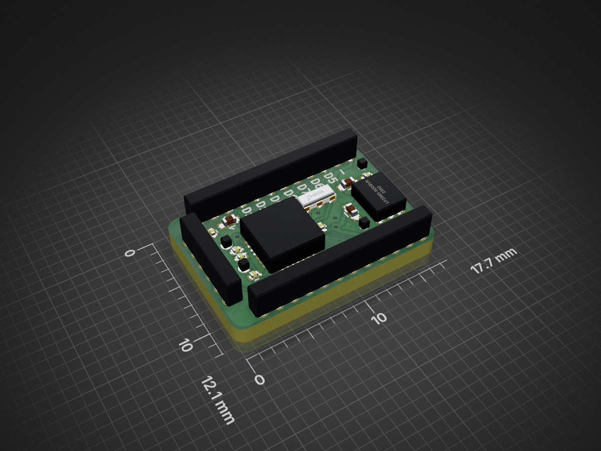
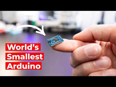
The MicroBit328 is an ultra-compact Arduino-compatible development board measuring just 11mm × 16mm - small enough to fit on your fingertip.
Microbit 0.6 is an open-source printed circuit board by StuckAtPrototype, from the StuckAtPrototype/MicroBit328 repository on GitHub. It is a 2-layer board of 17.7 × 12.1 mm with 23 parts on 30 nets, routed with 188 tracks and 6 vias.
It is built around the LP2985-50DBVR. Its parts include 6 capacitors, 3 resistors, 3 connectors, 2 ICs and 2 diodes.
The World's Smallest Arduino Compatible Board

The MicroBit328 is an ultra-compact Arduino-compatible development board measuring just 11mm × 16mm - small enough to fit on your fingertip. Despite its tiny footprint, it packs the full power of an Arduino Uno, making it perfect for space-constrained projects.
This project was originally designed in 2014 as a Kickstarter campaign that never launched. After 11 years, it's now open-sourced under the Apache License 2.0 for the maker community to build, modify, and use freely.
⚠️ Project Status: This project is no longer actively supported, but the designs remain relevant. All files are provided as-is for the community to use, modify, and build upon.
In 2014, Arduino was at the peak of its popularity. While Arduino boards were powerful and easy to use, they were simply too large for many compact projects. The MicroBit328 was born from the need for a truly miniature Arduino-compatible board.
After months of iteration, countless design revisions, and working with extremely small 0201 components (requiring assembly under a microscope), the board was ready. The Kickstarter campaign was prepared, graphics were made, and everything was set to launch.
However, due to employment contract restrictions at the time, the project was put on hold. Now, 11 years later, the MicroBit328 is finally being open-sourced so that anyone can build and use this tiny powerhouse.
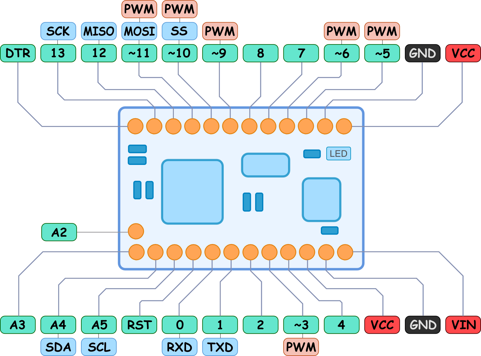
The board features standard Arduino Uno pinout (minus 2 pins), allowing you to:
The project includes several expansion shields to extend functionality. Note: Most shields were created using Fritzing, and some shields are unfinished or in various stages of completion.
Note: Shield designs are provided as-is. Some may require completion or verification before use in production.
⚠️ Warning: This board uses 0201 components (0.6mm × 0.3mm), which are extremely small and require:
Choose a Version: The latest version (0.6) is available in KiCad format. Earlier versions (0.1-0.5) are available in Fritzing format. Most shields were also designed in Fritzing.
Order PCBs: Use the Gerber files in the gerber/ folders to order PCBs from your preferred manufacturer.
Source Components: Refer to the schematic and BOM (Bill of Materials) for component requirements:
Assembly:
Programming:
Once assembled and programmed:
MicroBit/
├── version 0.6 328 - kicad/    # Latest KiCad design files
├── version 0.5 328/            # Version 0.5 with Gerber files
├── version 0.4 328/            # Version 0.4 with Gerber files
├── version 0.2 328/            # Version 0.2 with Gerber files
├── version 0.1 328/            # Initial version
├── shields/                     # Expansion shields
│   ├── FTDI USB plug in shield/
│   ├── Free IMU v.0.1/
│   ├── I2C shield v.0.1/
│   ├── RGB LED v.0.1/
│   ├── servo shield v.0.1/
│   └── ...
└── png's/ # Documentation imagesThis project is licensed under the Apache License 2.0. See the LICENSE file for details.
You are free to:
While this project is no longer actively maintained, contributions are still welcome! Whether it's:
Feel free to submit pull requests or open issues.
I'll monitor the issues, but I am unlikely to fix them.
Happy Making! 🚀

| Qty | Value | Footprint | References |
|---|---|---|---|
| 6 | VAL** | custom:STICHING_VIA | STICHING_VIA11, STICHING_VIA13, STICHING_VIA14, STICHING_VIA15, STICHING_VIA22, STICHING_VIA23 |
| 4 | 0.1uF | Capacitors_SMD:C_0201 | C1, C2, C3, C6 |
| 2 | 2.7k | Capacitors_SMD:C_0201 | R1, R3 |
| 1 | custom:Atmega328p_MMHR | U1 | |
| 1 | 10k | Capacitors_SMD:C_0201 | R2 |
| 1 | 16MHz | custom:CSTCE16M0V53-R0 | Q1 |
| 1 | 1uF | Capacitors_SMD:C_0402 | C4 |
| 1 | 2.2uF | Capacitors_SMD:C_0402 | C5 |
| 1 | BLUE | custom:LED_0402 | D2 |
| 1 | FTDI | custom:Header_50mil_6 | J3 |
| 1 | LP2985-50DBVR | custom:LP2985-50DBVR | U2 |
| 1 | MB_Header_12_A | custom:Header_50mil_12 | J1 |
| 1 | MB_Header_12_B | custom:Header_50mil_12 | J2 |
| 1 | RED | custom:LED_0402 | D1 |
It measures 17.7 × 12.1 mm and has 2 copper layers, 1.6 mm thick.
23 parts, built around the LP2985-50DBVR. The full list of its parts is on this page, with links to each part's symbol and footprint where PCBKit's library has them.
From the StuckAtPrototype/MicroBit328 repository on GitHub, at the commit this page was made from: the board is version 0.6 328 - kicad/microbit 0.6.kicad_pcb. PCBKit opens the board in the browser, with nothing to install.
Its repository states no licence, so its author keeps all rights: ask StuckAtPrototype before reusing the design.

brown-studios/minuet
Minuet upgrades your MAXXAIR Maxxfan with a brushless DC motor, home automation features, and accessories.

kaanpars/16_channels_eeg_card
I designed cards both in INA333 + TLV4333 and ADS1299. It is up to you which analog or digital output you should want to get. Importing restrictions in Turkey dragged me to designing my own sensor cards. ENJOY!


google/mozc-devices
Circuit diagrams and firmware source code for Gboard DIY keyboards


