2 layers238 × 174 mm
 stkdiretto/uulmduino3
Eine Mischung aus Diavolino und TV-B-Gone für den Girls'Day an der Uni Ulm
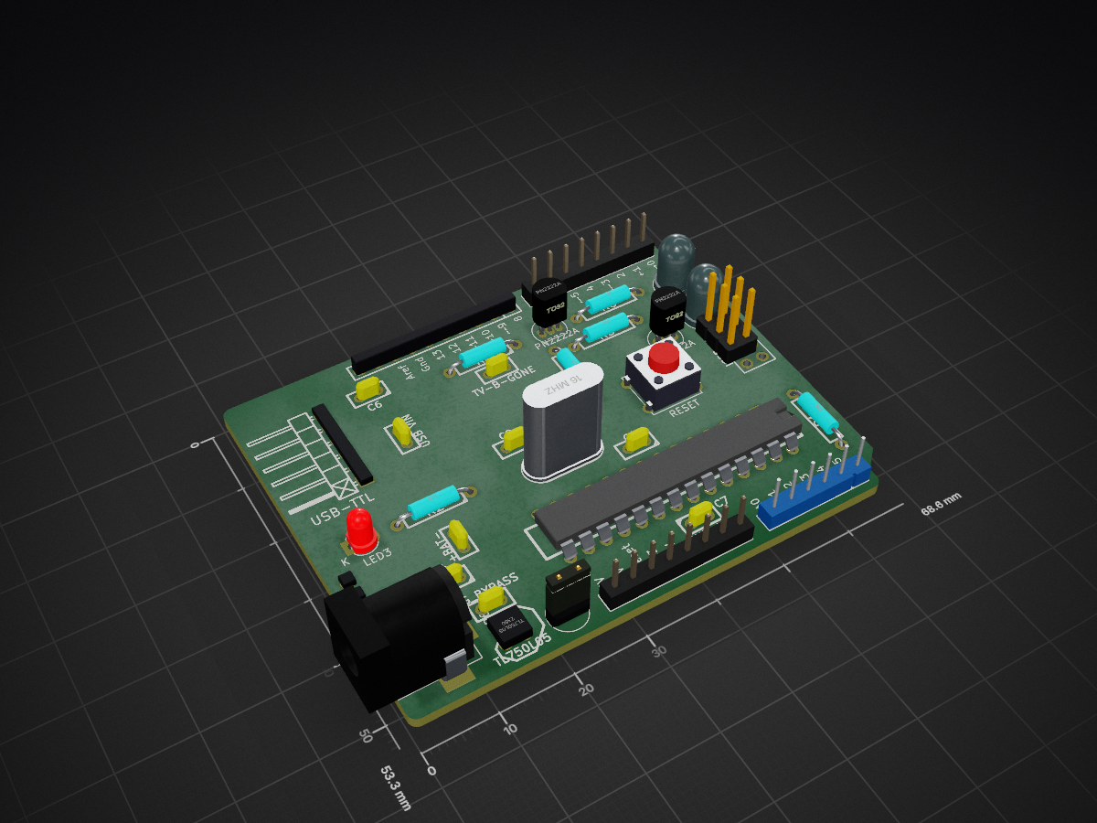
Uulmduino v2 20150826 is an open-source printed circuit board by stkdiretto, from the stkdiretto/uulmduino repository on GitHub. It is a 2-layer board of 68.6 × 53.3 mm with 36 parts on 40 nets, routed with 256 tracks and 2 vias.
It is built around the ATMEGA328-PU, TL750L05CD and PN2222A. Its parts include 7 capacitors, 6 resistors, 5 connectors, 3 diodes and 2 ICs. It belongs with the AVR (ATmega, ATtiny) boards of this library.


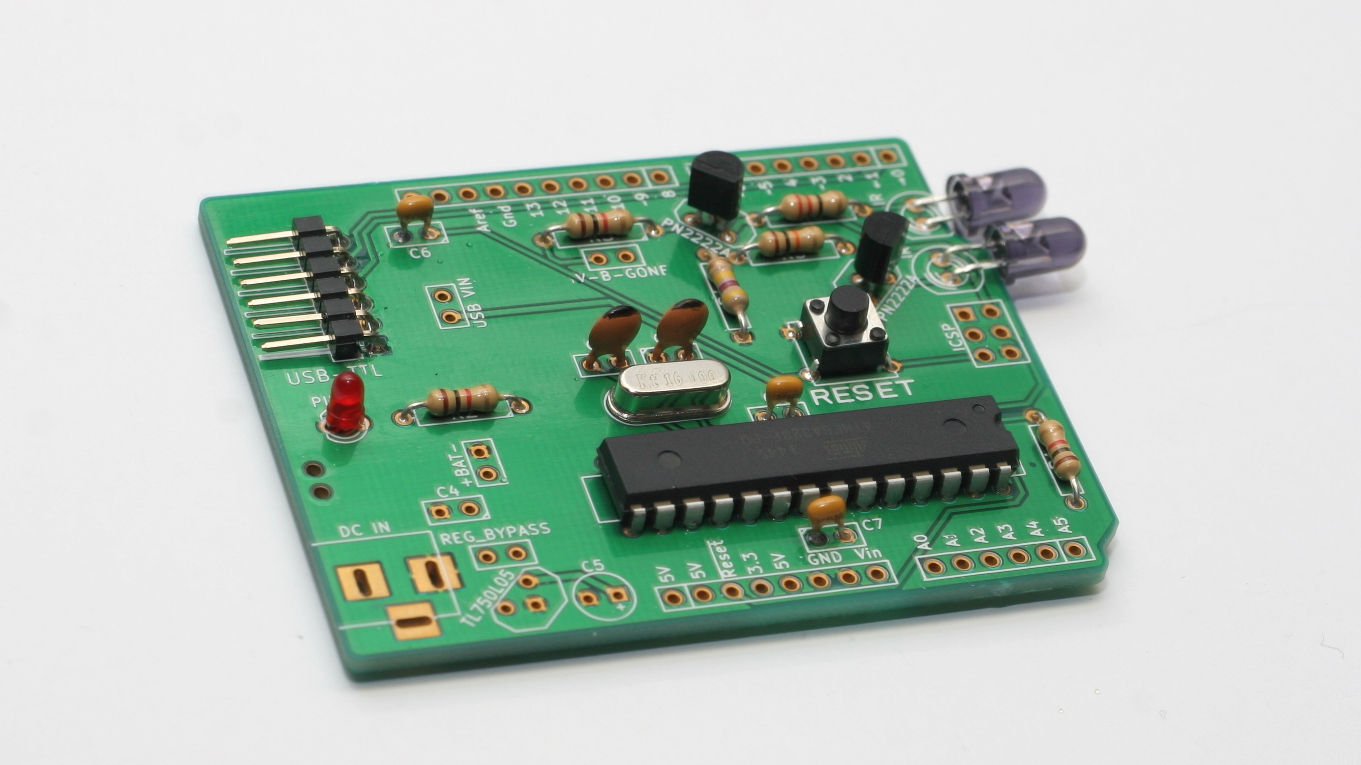
Eine Mischung aus Arduino (besser gesagt dem Diavolino von Evil Mad Scientist Labs) und der TV-B-Gone-Version von Ken Shirriff. Auf Basis des Diavolino und mit Hilfe des Sparkfun Inventors' Kit von der Arbeitsgruppe WissenSchaffer entwickelt für den Girls'Day 2015 an der Uni Ulm.
Das Handbuch ist im Ordner "handbuch" und liegt als Markdown vor. Es kann mit Pandoc nach PDF exportiert werden:
pandoc anleitung.md -o anleitung.pdf --latex-engine=xelatex --variable geometry="a5paper" --variable mainfont="Droid Sans"
Wer das Projekt nachmachen möchte, findet im handbuch-Ordner auch eine skizzenhafte Anleitung, was hinter den Kulissen passieren muss. Pull-Requests zur Verbesserung sind gerne gesehen!
| Qty | Value | Footprint | References |
|---|---|---|---|
| 4 | 0.1µF | Discret:C1 | C1, C4, C6, C7 |
| 2 | 10k | Discret:R4 | R1, R4 |
| 2 | 18pF | Discret:C1 | C2, C3 |
| 2 | CONN_8 | arduinoheaders:HEADER_100MIL_1R8P_PTH | P2, P4 |
| 2 | IR | LEDs:LED-5MM | LED1, LED2 |
| 2 | P*** | arduinoheaders:1pin_mechanical | 1PIN, 1PIN |
| 2 | PN2222A | Housings_TO-92:TO-92_Inline_Narrow_Oval | Q1, Q2 |
| 1 | 100 | Discret:R4 | R5 |
| 1 | 10µF | Discret:C1V5 | C5 |
| 1 | 16 MHz | Crystals:Crystal_HC49-U_Vertical | X1 |
| 1 | 1k | Discret:R4 | R2 |
| 1 | 220 | Discret:R4 | R6 |
| 1 | ATMEGA328-P | Sockets_DIP:DIP-28__300 | IC1 |
| 1 | BATTERY IN | Connect:SIL-2 | +BAT- |
| 1 | CONN_10 | arduinoheaders:HEADER_100MIL_1R10P_PTH | P1 |
| 1 | CONN_3X2 | arduinoheaders:pin_array_3x2 | ICSP |
| 1 | CONN_6 | Pin_Headers:Pin_Header_Angled_1x06 | USB-TTL |
| 1 | CONN_6 | arduinoheaders:HEADER_100MIL_1R6P_PTH | P3 |
| 1 | DC JACK | Connect:BARREL_JACK | P6 |
| 1 | LOGO | LOGO | G*** |
| 1 | PIN13 | LEDs:LED-3MM | LED3 |
| 1 | R | Discret:R4 | R3 |
| 1 | RESET | Buttons_Switches_ThroughHole:SW_PUSH_SMALL | SW1 |
| 1 | Regulator bypass | Connect:SIL-2 | REG_BYPASS |
| 1 | TL750L05 | Discret:LM78XX-TO92 | U1 |
| 1 | TV_B_GONE | Connect:SIL-2 | TV-B-GONE |
| 1 | VCC USB | Connect:SIL-2 | USB VIN |
It measures 68.6 × 53.3 mm and has 2 copper layers, 1.6 mm thick.
36 parts, built around the ATMEGA328-PU, TL750L05CD and PN2222A. The full list of its parts is on this page, with links to each part's symbol and footprint where PCBKit's library has them.
From the stkdiretto/uulmduino repository on GitHub, at the commit this page was made from: the board is hardware/rev2/uulmduino_v2_20150826.kicad_pcb. PCBKit opens the board in the browser, with nothing to install.
Its repository states no licence, so its author keeps all rights: ask stkdiretto before reusing the design.

SyedIhteshamuddin/All-Arduino-Projects
Embedded systems, PCB design, and electronics projects documenting my journey toward Electrical Engineering.

skiselev/micro_8088
Micro 8088 - IBM XT Compatible Processor Board based on Faraday FE2010 chipset

Staacks/there.oughta.be
Projects featured on my blog at https://there.oughta.be


plusvic/simplebus2-intercom
General description of the Simplebus2 protocol used by some Comelit's intercoms. Hardware for retransmitting Simplebus2 messages over UART.

