2 layers47.2 × 69.1 mm
 SteveLRojas/usb_button_interface1
Interface module that maps 6 button inputs to keyboard keys
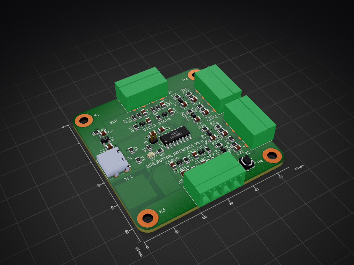
Usb button interface is an open-source printed circuit board by SteveLRojas, from the SteveLRojas/usb_button_interface repository on GitHub, published under the CERN-OHL-P-2.0 licence. It is a 2-layer board of 55 × 55 mm with 73 parts on 40 nets, routed with 357 tracks and 22 vias.
It is built around the CH552G, 74LVC1G17Z and MT9700. Its parts include 30 resistors, 20 capacitors, 10 ICs, 6 connectors and 1 diode. It belongs with the interfaces and adapters boards and the 8051 (CH55x, STC, AT89) boards of this library.


Interface module that maps 6 button inputs to keyboard keys.
Here you will find the design files for a small custom PCB that lets you connect buttons or switches to a PC via USB and map them to keyboard buttons.
The hardware is designed in KiCad, the design files are in the HW folder.
The firmware is written in C and meant to be compiled with Keil uVison C51 and linked with LX51. The project makes extensive use of pointers and requires a linker script for correct memory overlay.
The entire uVision project is in the FW folder.
The SW folder contains test scripts as well as a command line tool (ubi_programmer.py) used to set the key mapping. To set the key mapping you need ubi_programmer.py, ubi_platform.py, and ubi_regs.py. The other files are test scripts.
First you will need the hardware, boards can be ordered from JLCPCB and all the components are available from LCSC.
Once you have working hardware close the jumper J6 to put it in programming mode, compile the firmware, and use WCHISP or a similar program to upload the firmware.
After the firmware is uploaded remove jumper J6 to put the device in functional mode. Now when it is plugged into USB the LED will blink and then stay on, this means the device is in functional mode.
Touching the capacitive touch button will make the LED turn off, this means the device is in configuration mode. Touching the button again will put the device back into functional mode.
Note that the capacitive button is automatically calibrated each time the device is powered on, so while powering on the device make sure it is placed in its normal operating position and don't touch the capacitive button.
When the device is in functional mode it should appear to the PC as a completely satandard USB keyboard, when it is in configuration mode it will appear as a CDC ACM device.
There is no need to specify a serial port when running the configuration script, as it can scan the serial ports and automatically find the device.
Use the provided python script (ubi_programmer.py). Run it with -h to see what arguments it supports.
Example usage: python ubi_programmer.py --eeprom --sw0 0x1A --sw1 0x29
The above example maps sw0 to the 'W' key, and sw1 to the escape key. The hexadecimal numbers representing each keyboard key can be found in the document "HID Usage Tables for Universal Serial Bus (USB)".
The first time you configure the device you should specify all the switches (even if you don't intend to use them) to make sure nothing is mapped to an invalid key.
| Qty | Value | Footprint | References |
|---|---|---|---|
| 11 | 0.1u | Capacitor_SMD:C_0805_2012Metric | C1, C2, C3, C7, C8, C9, C11, C13, C15, C17, C18 |
| 10 | 10k | Resistor_SMD:R_0805_2012Metric | R1, R6, R11, R12, R13, R14, R23, R24, R25, R26 |
| 9 | 1k | Resistor_SMD:R_0805_2012Metric | R5, R7, R8, R9, R10, R19, R20, R21, R22 |
| 8 | 0 | Resistor_SMD:R_0805_2012Metric | R15, R16, R17, R18, R27, R28, R29, R30 |
| 8 | 0.01u | Capacitor_SMD:C_0805_2012Metric | C10, C12, C14, C16, C19, C20, C21, C22 |
| 8 | 74LVC1G17 | Package_TO_SOT_SMD:SOT-353_SC-70-5 | U3, U4, U5, U6, U7, U8, U9, U10 |
| 4 | Conn_01x04 | Connector_Phoenix_MC:PhoenixContact_MC_1,5_4-G-3.81_1x04_P3.81mm_Horizontal | J2, J3, J4, J5 |
| 4 | MountingHole_Pad | MountingHole:MountingHole_3.2mm_M3_Pad | H1, H2, H3, H4 |
| 2 | 5K1 | Resistor_SMD:R_0805_2012Metric | R2, R3 |
| 1 | 1u | Capacitor_SMD:C_0805_2012Metric | C6 |
| 1 | 4.7k | Resistor_SMD:R_0805_2012Metric | R4 |
| 1 | CH552G | Package_SO:SO-16_3.9x9.9mm_P1.27mm | U1 |
| 1 | Conn_01x02 | Connector_PinHeader_1.27mm:PinHeader_1x02_P1.27mm_Vertical | J6 |
| 1 | MT9700 | Package_TO_SOT_SMD:SOT-23-5 | U2 |
| 1 | ORANGE | LED_SMD:LED_0805_2012Metric | D1 |
| 1 | SW_Push | Button_Switch_SMD:SW_SPST_PTS810 | SW1 |
| 1 | TestPoint_Flag | Signetics:CapTouch_10mm | TP1 |
| 1 | USB_C_Receptacle_USB2.0 | Connector_USB:USB_C_Receptacle_HRO_TYPE-C-31-M-12 | J1 |
It measures 55 × 55 mm and has 2 copper layers, 1.6 mm thick.
73 parts, built around the CH552G, 74LVC1G17Z and MT9700. The full list of its parts is on this page, with links to each part's symbol and footprint where PCBKit's library has them.
From the SteveLRojas/usb_button_interface repository on GitHub, at the commit this page was made from: the board is HW/V1.0/usb_button_interface.kicad_pcb and its schematic HW/V1.0/switch_debounce.kicad_sch. PCBKit opens the board in the browser, with nothing to install.
Its repository publishes it under the CERN-OHL-P-2.0 licence: you may reuse it on that licence's terms (keep the author's notice, and for a copyleft licence share your changes alike).

SteveLRojas/PS2_to_USB_Converter
A converter for connecting a PS/2 keyboard to a USB host


zephray/NekoInk
Next gen. of NekoCal: An open-source hackable and programmable e-paper display


NVIDIA-AI-IOT/my-jetson-nano-baseboard
An open source Jetson Nano baseboard and tools to design your own.

Smoothieware/Smoothieboard2
Hardware files for the Smoothieboard v2, and extension boards