2 layers140.5 × 30 mm
Type e
google/mozc-devices
Circuit diagrams and firmware source code for Gboard DIY keyboards
16 parts3kApache-2.0

 stathopulos/updi
UPDI and UART Serial Programmer
Updi is an open-source printed circuit board by stathopulos, from the stathopulos/updi repository on GitHub. It is a 2-layer board of 22 × 22 mm with 16 parts on 19 nets, routed with 112 tracks and 5 vias.
Its parts include 6 capacitors, 4 resistors, 2 ICs, 1 diode and 1 connector. It belongs with the interfaces and adapters boards of this library.
A low cost USB programmer for interfacing with both UPDI and UART from the same board
Unlike other UPDI programmers, this board allows access to both UART and UPDI without having to change the wiring between your programmer and MCU, making it easy to go from programming to reading debug data over serial.
This design makes heavy use of the JLC basic parts library to keep BOM costs down. At volumes as low as 25 units this board can be completed, assembled, and shipped for under $3 per board.
| Front | Back |
|---|---|
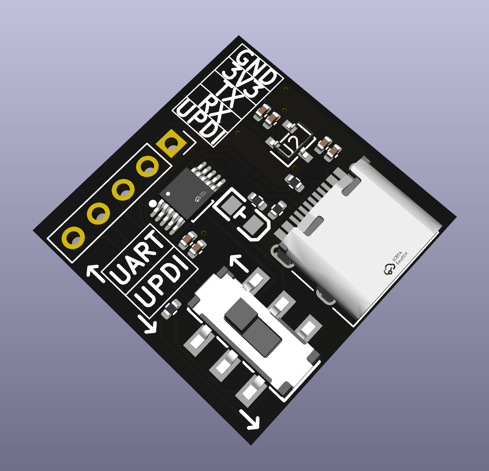 | 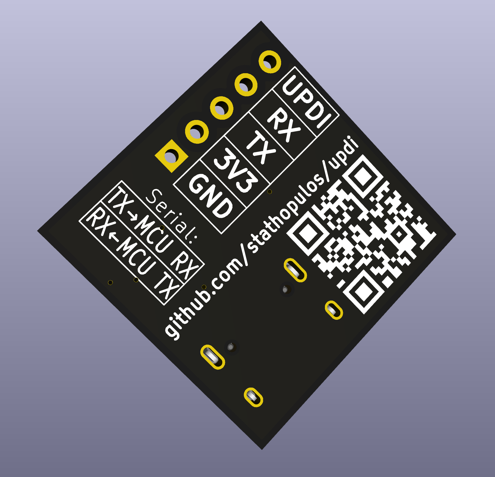 |
| Qty | Value | Footprint | References |
|---|---|---|---|
| 6 | 2.2uF | Capacitor_SMD:C_0402_1005Metric | C1, C2, C3, C4, C5, C6 |
| 2 | 5.1k | Resistor_SMD:R_0402_1005Metric | R2, R3 |
| 1 | 1k | Resistor_SMD:R_0402_1005Metric | R1 |
| 1 | 330R | Resistor_SMD:R_0402_1005Metric | R4 |
| 1 | Conn_01x05 | Connector_PinSocket_2.54mm:PinSocket_1x05_P2.54mm_Vertical | J1 |
| 1 | SW_DPDT | EasyEDA_Lib:SW-SMD_MST22D18G2 | SW2 |
| 1 | ~ | EasyEDA_Lib:SOT-23-3_L2.9-W1.6-P1.90-LS2.8-BR | U2 |
| 1 | ~ | EasyEDA_Lib:MSOP-10_L3.0-W3.0-P0.50-LS5.0-BL | U1 |
| 1 | ~ | EasyEDA_Lib:LED0805-RD | LED1 |
| 1 | ~ | USB:USB_C_Receptacle_HRO_TYPE-C-31-M-12 | USB1 |
It measures 22 × 22 mm and has 2 copper layers, 1.6 mm thick.
16 parts. The full list of its parts is on this page, with links to each part's symbol and footprint where PCBKit's library has them.
From the stathopulos/updi repository on GitHub, at the commit this page was made from: the board is pcb/updi.kicad_pcb and its schematic pcb/updi.kicad_sch. PCBKit opens the board in the browser, with nothing to install.
Its repository states no licence, so its author keeps all rights: ask stathopulos before reusing the design.
google/mozc-devices
Circuit diagrams and firmware source code for Gboard DIY keyboards

conorpp/u2f-zero
U2F USB token optimized for physical security, affordability, and style

rusefi/rusefi
rusefi - GPL internal combustion engine control unit

VoronDesign/Voron-Hardware
Cool Hardware designed by the Voron Design group

hoglet67/RGBtoHDMI
Bare-metal Raspberry Pi project that provides pixel-perfect sampling of Retro Computer RGB/YUV video and conversion to HDMI

hackclub/OnBoard
💡 Join 1,000 teenagers and make your first PCB with a $100 grant!

